meta-measured updates

I’ve been grinding down updates to meta-measured slowly but surely over these past few days. This was started a while back but slowed to a stop when I got distracted by work on meta-selinux. Last week my work to upgrade the SELinux toolstack was merged upstream so I’m re-focusing on getting meta-measured back in shape. This is a quick run down on the changes.

General Maintenance and Release Tracking

I haven’t been chasing upstream much so most of this work has just been maintenance. The kernel in OE has moved forward with 4.1 the new stable in master. The read-only root file system class was broken when I tried a fresh master build the other day. When jumping in to start a refresh, finding core features broken can be a bit discouraging. Instead of taking on this fix immediately I figured it would be best to create a branch to track the latest release (fido) and get that working first. I’ve always avoided tracking OE releases because I don’t want to give the impression that meta-measured is in any way “stable”, as if having my master branch broken on a regular basis wasn’t a good enough indicator.

Seriously though, I kinda dropped the “chasing master” ball. Having a branch that follows the latest release is a good way to make getting everything up to date and it’s a good insurance policy against future breakage in master. So win / win on that. Fido still has a functional readonly-rootfs class so, for the 2 other people out there who have kicked the tires on meta-measured, fall back to a release branch. My goal is to keep at least one release branch in working order.

There are two changes between fido and the current master that have an impact on meta-measured. The first is the upgrade to GCC5. For the trousers and tpm-tools packages this requires a patch that I’ve gratefully borrowed from the hardworking people over at the Debian project. The other is meta-intel nuking the meta-nuc layer. This is a pretty minor change and I’m now using the measured-intel-corei7-64 that extends the intel-corei7-64 machine from meta-intel on the master branch. Fido still has the NUC machine so I’ll stick to that for Fido.

systemd

The first external submission to meta-measured came in a few months back. This was to add systemd support to the trousers package. I had done something similar to this as part of some work to get meta-measured working with the Edison but it was in the BSP layer. It really shouldn’t have been in the BSP layer to begin and my implementation was a hack regardless. The patch I received that adds this feature directly to meta-measured was well done so I’ve added it directly and removed my hack from the BSP.

The only bit I didn’t like from the patch was a utility script that loaded every TPM module under /lib/modules/$(uname -r). This seems a bit heavy handed given that modern Linux kernels autoload these modules when the device is detected. Pretty minor change though and this is now in meta-measured proper.

IMA and TPM2

I started playing around with configuring IMA a while back as a way to exercise the TPM2 that’s baked into the Minnowboard Max as part of PTT. I don’t have any specific plans to do much with IMA just yet but with the xattrs patches I pushed into meta-selinux I’m hoping to be able to support IMA appraisal. It would be a great use case and demonstration to show the utility of my xattr work with an OE image booting with IMA appraisal enforced from firstboot.

UEFI Breakage

I’ve been saving the bad news for last unfortunately. Somewhere in the changes that have been going on with OE, my bringing meta-measured up to date and flashing the firmware on my IVB NUC, measured-image-bootimg broke. I’m pretty sure this is a problem with the latest firmware for the NUC but that’s a guess. Grub2 comes up OK but tboot doesn’t seem to take over.

In prevous debugging I learned that tboot won’t log to VGA since UEFI doesn’t setup a text console for use by whatever executes after ExitBootServices() is called. It’s frame buffer only in UEFI world I guess. But tboot would still log to a serial device through direct I/O. Not this time though. Once Grub2 kicks off tboot my NUC is unresponsive and I get no additional output. Booting straight to the kernel from grub works fine but going the tboot route through multiboot2 isn’t working.

I’m pretty much out of debugging ideas here. My test system is getting a bit old and it’s the only UEFI system I have for use here so I’m writing this off as a loss for the time being. If anyone out there is testing this on a UEFI system I’d love to hear about whatever results you have to report.

Next steps

I’ve added the contributed systemd support to trousers but I haven’t enabled or tested systemd support for my reference images. This is next on my list of things to do. I’ve got trousers working on a systemd driven image previously in some work to wire a TPM up to an Edison system (more on this in the future hopefully) but I was working on on the reference Edison images. Stay tuned and hopefully I’ll have proper systemd support in the near future.

Attaching a TPM on the LPC

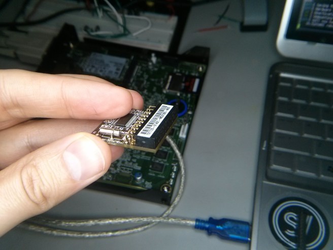
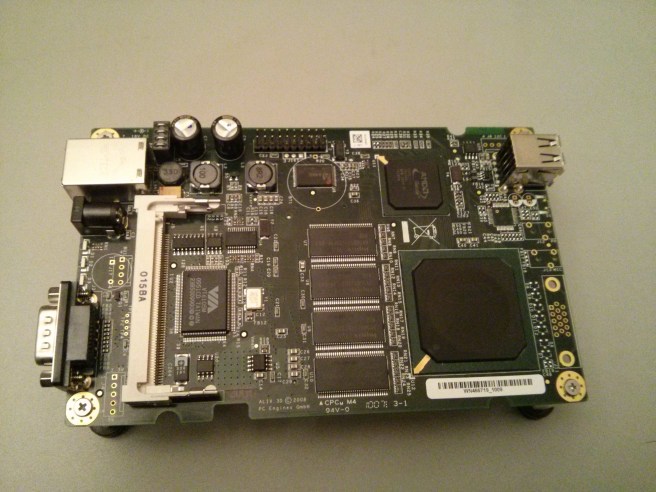
Just for the funs I recently revived some older work with my PCEngines alix3d2 where I built an OE meta layer with a simple machine and kernel config to build images: meta-alix.

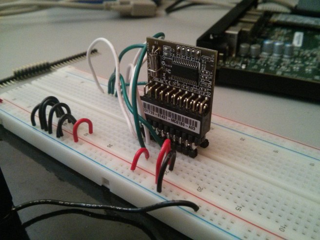
IMG_20150213_151432

IMG_20150216_183119

IMG_20150216_183320

TPMs for all the boards!

I’ve got a soft spot for the older PCEngines WRAP board since it was the first platform I experimented on while building a home router / access point years ago. So meta-alix was fun work but nothing too crazy. While playing around with this I noticed that the alix3d2 has an exposed 20 pin header labeled ‘LPC’. Now that is interesting because I’ve got a few Asus branded Infineon TPMs laying about and they’ve got LPC connectors on them. A home wireless router with a TPM on it? Now that could be interesting.

Attaching an TPM designed to attach to a board on a 20 pin LPC connector should be pretty easy right? That’s what I thought too. But here we are 2 weeks later and I’m just now getting to write this up and I can’t say this work was 100% successful. But before I go too deep into the trials and tribulations let’s start with a bill of materials.

Bill of materials

To start out you’ll need a TPM and one designed to attach to your system on the LPC bus. TPMs are a PITA to buy really. There are 3 main companies that manufacture them but you can’t buy them direct. Thankfully there are some motherboard manufacturers out there that support the TPM via a “daughter-card” and from my experience this is mostly the high end manufacturers like Asus and Supermicro. I had 2 Asus TPMs laying around so this seemed like a good opportunity to put them to use. On Amazon these TPMs go for about $15 but when I bought mine almost a year ago they were less than half that.

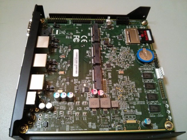
The system that started out trying to attach this thing to is an alix3d2. I also picked up one of the newer PCEngines APU but *spoiler alert* only after I had serious problems getting the alix to work.

You’ll also need a soldering iron and the usual soldering / prototyping gear on hand (lights, wire, solder, magnifying glass etc). That’s right I said soldering. It’s been a while for me too. Like 10 years. Don’t worry there isn’t much too this and it was really fun.

Prototyping

As you’ve likely guessed by now, just because a system has an LPC connector doesn’t mean this thing is plug and play. The Asus TPM daughter card has pin 4 blocked / keyed and the ALIX doesn’t so that’s our first hint. The real data is in the respective pin diagrams. Finding these isn’t as easy as I’d hoped so I had to do some digging.

The docs for the ALIX systems are all on the PCEngines website so that part’s easy. The Asus TPM doesn’t seem to have any docs though. If you take the time to dig into the boards that support them though you’ll find the manuals for these boards have the pin assignment documented. I pulled down the manual for the P9D-WS and used this as a reference. Page 2-29 has what we’re looking for.

Pin Layouts

With the pin layouts in hand we can see clearly that plugging the TPM daughter card directly into the board isn’t gonna happen. I’ll reproduce the layouts here so we can view them side by side:

Asus TPM PCEngines LPC
pin signal signal
1 PCICLK PCICLK</td
2 GND GND
3 FRAME LAD0
4 BLOCKED GND
5 PCIRST# LAD1
6 NC GND
7 LAD3 LAD2
8 LAD2 GND
9 +3V LAD3
10 LAD1 GND
11 LAD0 LFRAME#
12 GND GND
13 NC PCIRST#
14 NC CLK48A
15 +3VSB ISP
16 SERIRQ Vcc (+5V)
17 GND GND
18 CLKRUN V3
19 PWRDWN SERIRQ
20 NC LDRQ#

There’s basically no overlap in the pin layouts here except for a few ground connections. This blew my mind at first but after searching through the Intel Low Pin Count Interface Specification it turns out that this bus was intended for use on-board only and so there’s no pin layout specified for external connectors. First mystery solved. Now let’s figure out how we’re gonna wire this thing up.

To the breadboard!

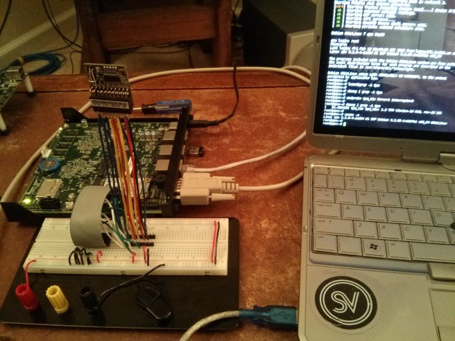
This isn’t going to be as easy as “plug and play” but it’s not far off. We just need to connect the right pins. With the pin map above and a little help from the spec (to get the minimum required connections) we can pull out our breadboard and prototype this thing.

If you’re like me you’ll have to go out and buy materials as you need them. Luckily I live minutes away from HSC Electronic Supply which is an amazing surplus electronic shop. After an hour or 3 poking around the piles of old electronic gear I managed to scrounge up a 20 pin ribbon cable with a connector that looked like it might fit on my breadboard. With a 20 pin DIP ribbon cable connector I had what I needed to connect the alix to the breadboard.

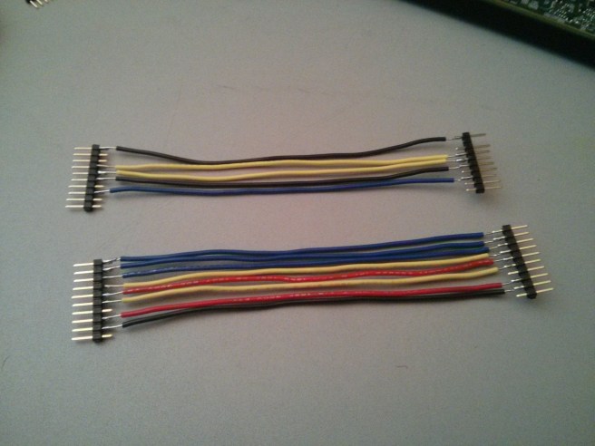
Next was to get the TPM daughter card wired up to the breadboard. This was harder than I expected. I couldn’t easily find a connector that would suit this purpose that didn’t require waiting for shipping. So I soldered some wires up to breakaway headers and rigged up a horrible TPM-to-breadboard connector. Then we just hook up the two using the following mapping:

TPM ALIX Signal
1 1 PCICLK / LCLK: 33MHz clock
3 11 LFRAME#: Transaction signal
5 13 LRESET#: Bus reset. AKA PCIRST#
7 9 LAD3: Data lane
8 7 LAD2: Data lane
9 & 15 18 3 Volts DC
10 5 LAD1: Data lane
11 3 LAD0: Data lane</td
16 19 SERIRQ: Serialized interrupt signal

After some fiddling (kicking, screaming and burning myself with a soldering iron) this is what it looked like:

IMG_20150213_093921

IMG_20150212_175548
Now it SHOULD have worked. These are the right connections. But on the alix3d2 I got no love. I didn’t actually get this set-up to work till my apu1d showed up in the mail 3 days later. For whatever reason the external LPC on the alix3d2 just doesn’t work as advertised. Without an oscilloscope I can’t debug much beyond whether the voltage and ground pins are OK (and they are) so for now that will remain a mystery. So the alix3d2 is out and the apu1d is in.

Anyways we can do better than this bootleg breadboard setup. Let’s see about cleaning it up.

IMG_20150213_093453
IMG_20150213_093638

Clean it up

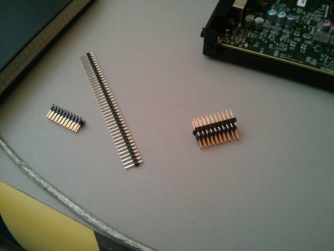
The wiring above was super flaky and that shouldn’t be a surprise. I didn’t get the length of each wire exact and the pins slipped around a bit in the plastic. I ordered some IDC breakout helpers from Adafruit but they were garbage. They plug into the breadboard fine but the pins aren’t long enough and they just pop back out immediately.

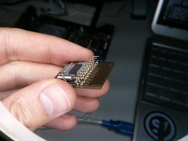
So again I hacked up another connector out of DIP/DIL headers and some breakaway headers spaced to span the gap in the breadboard. This is generally a bad idea since the solder is what’s holding the whole thing together but it worked out pretty OK:

IMG_20150213_151417

IMG_20150216_183250

IMG_20150214_134235

Packaging for the APU enclosure

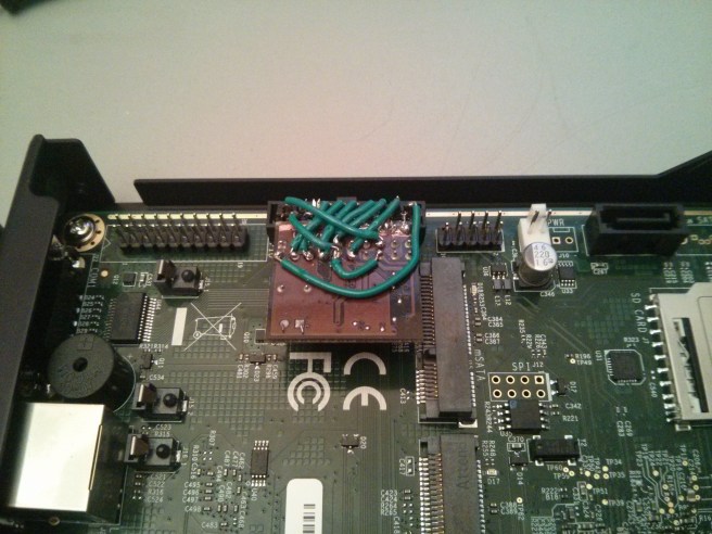
After convincing ourselves that the wiring above is right on the breadboard we need to clean this up so that it fits in the enclosure with the APU. There’s not a lot of space in the PCEngines recommended case1d2 but there’s enough if we’re sufficiently inventive. And by “inventive” I mean “you’ve got a hacksaw”.

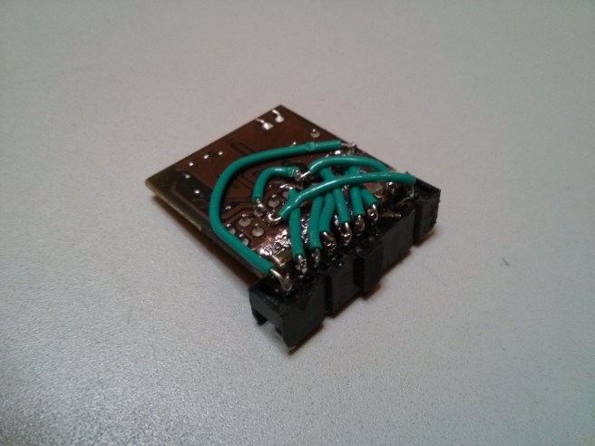
Start out by removing the female header from the TPM and trim back the connector pins. If we flip this header on it’s side we can use it to mount the TPM once we reconnect it. This would require either unblocking pin 4 on the connector or cutting pin 4 off of the APU board. Since pin 4 on the APU is ground anyways this shouldn’t be a problem.

I used a 20 pin DIP to ribbon cable connector for my setup. I sanded down the daughter board to expose the copper on the base which happens to be ground and connected this with the even pins on the connector up through 12. This proved to be a pretty solid base as it holds the daughter board nice and tight to the connector.

Then we just cut wires and solder pins per the table above. The wire I had on hand was 28 gauge which was a bit too big and the soldering job is straight up ugly in spots but it’s the first bit of soldering I’ve done in 10 years so that’s good enough for me. I’ve got another TPM on hand so I’ll have another go now that I’ve had some practice.

Testing

I used both a Debian install with the tpm-tools package to test this as well as the core-image-tpm from meta-measured. I’d recommend sticking with Debian unless you feel like falling down the rabbit hole of an OE build. The important thing to keep in mind is that the APU BIOS doesn’t support the TPM so it won’t do the necessary setup for us.

The BIOS is supposed to do a number of things to set things up so that the OS can use the TPM. This includes running the TPM self test, enabling it and setting up ACPI entries to make it easy for the OS to talk to it. With the stock BIOS on the APU we won’t get any of this. Thankfully the number of platforms that have implemented TPM support wrong in the BIOS over the years is quite high so the Linux TPM TIS driver can do all of this for us if we give it the right parameters:

root@apu:~# modprobe tpm_tis force=1
[   74.027383] tpm_tis tpm_tis: 1.2 TPM (device-id 0xB, rev-id 16)
[   74.063388] tpm_tis tpm_tis: Issuing TPM_STARTUP
[   74.260392] tpm_tis tpm_tis: TPM is disabled/deactivated (0x7)
[   74.308465] genirq: Flags mismatch irq 4. 00000080 (tpm0) vs. 00000000 (serial)
[   74.315956] tpm_tis tpm_tis: Unable to request irq: 4 for probe
[   74.436459] genirq: Flags mismatch irq 8. 00000080 (tpm0) vs. 00000000 (rtc0)
[   74.443753] tpm_tis tpm_tis: Unable to request irq: 8 for probe

The modinfo command will tell you all of the gory details about what these parameters do if you’re interested. The short version is that force=1 causes the driver to ignore ACPI and probe for the TPM device. You can also add the interrupts=0 argument to disables interrupts which will get rid of all of the genirq errors. After this you should see /dev/tpm0 appear magically. You can then start tcsd and get some version info out of the TPM:

root@apu:~# tpm_version 
  TPM 1.2 Version Info:
  Chip Version:        1.2.3.19
  Spec Level:          2
  Errata Revision:     2
  TPM Vendor ID:       IFX
  Vendor Specific data: 0313000b 00
  TPM Version:         01010000
  Manufacturer Info:   49465800

You won’t be able to do much more than this though since the BIOS hasn’t enabled the TPM for us. We’ll get past this in my next post.

TXT and tboot on the IVB NUC

I wrote a few days back about getting serial output from tboot on my new-ish Ivy Bridge vPro NUC. This was a means to and end and so this is where we’ll cover actually using this serial hardware to do something meaningful.

tboot log from the DC53427HYE NUC

Testing TXT and tboot on a new system is often painful. If there’s something wrong and tboot can’t execute SENTER successfully the system just reboots and will continually. This confuses the hell out of most and necessitates either serial hardware to capture log output for trouble shooting, or a patch to bypass this reboot logic.

The bit about the patch is interesting and I’ve hacked one out here. I hacked this together without much thought about the security implications as a work-around so I don’t recommend it for production use. It was only intended as a way to bring up a system with a borked TXT implementation so data could be collected with txt-stat.

Regardless of how you go about getting your tboot output it’s your first step in debugging. Here’s the tboot log captured from my DC53427HYE NUC. You can see the automated reboot after SENTER fails.

Debugging my tboot failure

I’ve jacked up the logging level of tboot so there’s a lot of data go dig through in the log. Generally though the data we need is in the TXT.ERRORCODE. Don’t forget though that on the first boot this value will be 0x0 since it’s only set once the failure occurs. The interested reader can, well, read all about this register in the MLE developers guide section B.1.3.

So after the failed boot the TXT.ERRORCODE gets set and we can grab it from the log. The relevant line is:

TBOOT: TXT.ERRORCODE: 0xc0021041

Not a particularly helpful error message but then again, there isn’t much space for a helpful textual description of the error in a 32bit register. So the next step is to decode this thing.

Decoding the TXT.ERRORCODE

The MLE developers guide describes the general structure of the data in this register but the error code itself is specific to the ACM used by the platform. Again this data is in the tboot log file:

TBOOT: checking if module /acm_hsw.bin is an SINIT for this platform...
TBOOT: chipset production fused: 1
TBOOT: chipset ids: vendor: 0x8086, device: 0xb001, revision: 0x1
TBOOT: processor family/model/stepping: 0x306a9
TBOOT: platform id: 0x10000000000000
TBOOT:   1 ACM chipset id entries:
TBOOT:       vendor: 0x8086, device: 0xb002, flags: 0x1, revision: 0x1, extended: 0x0
TBOOT:   chipset id mismatch
TBOOT: checking if module /acm_ivb.bin is an SINIT for this platform...
TBOOT:   1 ACM chipset id entries:
TBOOT:       vendor: 0x8086, device: 0xb001, flags: 0x1, revision: 0x1, extended: 0x0
TBOOT:   4 ACM processor id entries:
TBOOT:       fms: 0x206a0, fms_mask: 0xfff3ff0, platform_id: 0x10000000000000, platform_mask: 0x1c000000000000
TBOOT:       fms: 0x206a0, fms_mask: 0xfff3ff0, platform_id: 0x4000000000000, platform_mask: 0x1c000000000000
TBOOT:       fms: 0x306a0, fms_mask: 0xfff3ff0, platform_id: 0x10000000000000, platform_mask: 0x1c000000000000
TBOOT: SINIT matches platform

You can see on line 1 that tboot is trying the HSW / Haswell ACM which doesn’t match the platform. Then on line 9 it gives the IVB / Ivy Bridge a try and that one matches the platform. So our error code is specific to the IVB ACM so we’ll have to dig through the docs from that tarball. If you’ve built meta-measured the appropriate PDF will be located at:

${TOPDIR}/tmp-glibc/work/corei7-64-oe-linux/3rd-gen-i5-i7-sinit/67-r0/3rd_gen_i5_i7-SINIT_67/SINIT_Errors.pdf.

But before we can make use of this we’ve gotta parse out the error code into its component parts. From this doc they’re defined as (from MSB to LSB):

  • bit 31 – Valid
  • bit 30 – External
  • bits 29:25 – Reserved
  • bits 24:16 – Minor Error Code
  • bit 15 – SW Source
  • bits 14:10 – Major Error Code
  • bits 9:4 – Class Code
  • bits 3:0 – Module Type

So we need to divide the error code 0xc0021041 on these boundaries and then go back to the docs to figure out what each field means:

Valid: 0x1 - The error code is valid.
External: 0x1 - Error state induced by external software.
Reserved: 0x0 - No significance. 
Minor Error Code: 0x2 - Fatal and TPM specific.
SW Source: 0x0 - Generated by the ACM.
Major Error Code: 0x4 - TPM NV is unlocked.
Class Code: 0x4 - TPM Access
Module Type: 0x1 - SINIT Module

Going through each of these takes a while so we’ll focus on the important stuff: The Major error code. Actually the error text says it all: The TPM NV RAM is unlocked and it shouldn’t be. With the TPM in this state tboot also complains in the boot log, see line 3 below from the log linked above:

TBOOT: TPM: TPM Family 0x0
TBOOT: TPM is ready
TBOOT: TPM nv_locked: FALSE
TBOOT: TPM timeout values: A: 750, B: 750, C: 750, D: 750

So there’s the problem. Now what’s the solution?

Unlocked TPM NVRAM

The TPM NVRAM is described in the relevant TCG TPM 1.2 spec, section 19: “NV Storage Structures”. The parts relevant to us is 19.1.1 where the required TPM_NV_INDEX values are described. These are the NV indexes that “must be found on each TPM regardless of platform”.

The first index listed in this section is TPM_NV_INDEX_LOCK and given the error code we’re getting that looks relevant. A bit of reading and you’ll see why having this index defined on a TPM is so important and why shipping a platform with it undefined is considered a security issue. Turns out that without this index defined the TPM doesn’t enforce authorization protections. In this state an attacker can write to the NVRAM repeatedly, wear it out (since NVRAM can be written to a finite number of times) and effectively DOS the TPM completely by making the NVRAM unusable. Very surprising that Intel is shipping the NUC in this state. Anyways, nothing we can’t fix …

At this point I went back in to the NUC and used tpm_nvinfo to dump the NVRAM indexes defined on my platform:

NVRAM index   : 0x10000001 (268435457)
PCR read  selection:
 Localities   : ALL
PCR write selection:
 Localities   : ALL
Permissions   : 0x00001002 (WRITEALL|OWNERWRITE)
bReadSTClear  : FALSE
bWriteSTClear : FALSE
bWriteDefine  : FALSE
Size          : 20 (0x14)

NVRAM index   : 0x1000f000 (268496896)
PCR read  selection:
 Localities   : ALL
PCR write selection:
 Localities   : ALL
Permissions   : 0x00020002 (OWNERREAD|OWNERWRITE)
bReadSTClear  : FALSE
bWriteSTClear : FALSE
bWriteDefine  : FALSE
Size          : 1129 (0x469)

NVRAM index   : 0x50010000 (1342242816)
PCR read  selection:
 Localities   : ALL
PCR write selection:
 Localities   : ALL
Permissions   : 0x00000001 (PPWRITE)
bReadSTClear  : FALSE
bWriteSTClear : FALSE
bWriteDefine  : FALSE
Size          : 10 (0xa)

NVRAM index   : 0x50000003 (1342177283)
PCR read  selection:
 Localities   : ALL
PCR write selection:
 Localities   : 0x18
Permissions   : 0x00000000 ()
bReadSTClear  : FALSE
bWriteSTClear : FALSE
bWriteDefine  : FALSE
Size          : 64 (0x40)

NVRAM index   : 0x50000001 (1342177281)
PCR read  selection:
 Localities   : ALL
PCR write selection:
 Localities   : ALL
Permissions   : 0x00002000 (WRITEDEFINE)
bReadSTClear  : FALSE
bWriteSTClear : FALSE
bWriteDefine  : FALSE
Size          : 54 (0x36)

I was hoping that the TPM_NV_INDEX_LOCK (defined in index 0xffffffff) would be missing and that defining it would solve my problem. From the output above you can see that it’s not listed. The only relevant data I could find on the web about defining this index was a post on the tboot devel list with somone trying to use the tpmj utility. Digging into all of that java seemed like way too much work so I gave the tpm_nvdefine utility a go:

root@intel-core-i7-64:~# tpm_nvdefine --index=0xffffffff --size=0
Successfully created NVRAM area at index 0xffffffff (4294967295).

Success! I had hoped then that executing tpm_nvinfo again would show this new index … but it doesn’t. So other than the “success” message from tpm_nvdefine we have no way of knowing whether or not the new index was actually defined. The easiest way to test this is to try booting with tboot again and hope that the error goes away. And it does:

TBOOT: TPM: TPM Family 0x0
TBOOT: TPM is ready
TBOOT: TPM nv_locked: TRUE
TBOOT: TPM timeout values: A: 750, B: 750, C: 750, D: 750

Conclusion

So that’s how you define the TPM_NV_INDEX_LOCK TPM index on your IVB NUC. This effectively locks the TPM NVRAM on a platform that ships with the the TPM NVRAM unlocked. Until now I had only seen this on Lenovo systems (lots of them) but I guess Intel is shipping platforms like this too. Having some automated way to detect and fix platforms in this state would be really nice …

OpenXT: Contingencies Abandoned

This post is long overdue. I’ve been experimenting with using OE as a means to building measured systems for a while now. Back before Openxt became a reality I was hedging bets and working on some overlapping tech in parallel. Now that OpenXT is available as OSS I’m going to abandon some of this work and shift focus to OpenXT. I do however feel like there should be some record of the work that was done and some explanation as to why I did it and how it relates to OpenXT.

Here goes …

Building systems with security properties

All of this nonsense began with some experimentation in using OE as a means to build measured systems. For some reason I think that a sound integrity measurement architecture is necessary for the construction of software systems with meaningful security properties. All of the necessary component parts were available as open source but there were few examples showing how they could be integrated into a functional whole. Those that did were generally research prototypes and weren’t maintained actively (need references). My work on meta-measured was the first step in my attempt to make the construction of an example measured system public and easily buildable.

Building a measured systems with the Xen hypervisor as a primary component was another part of this work. I wasn’t using virtualization for the sake of virtualization though. Xen was a means to an end: its architecture allows for system partitioning in part through the Isolated Driver Domain model like the example I describe here. The NDVM is just the “low hanging fruit” here but it serves as a good example of how OE can be used to build very small Linux VMs that can serve as example device domains. There are ways to build smaller IDDs but IMHO a Linux image < 100MB is probably the point of diminishing returns currently. Hopefully in the future this will no longer be the case and we'll have IDDs based on unikernels or even smaller things.

Small, single purpose systems are important in that they allow us to extend the integrity measurement architecture into more fine-grained system components. Ideally these IDDs can be restarted so that the integrity state of the system can be refreshed on a periodic basis. By disaggregating the Xen dom0 we increase the granularity of our measurements from 1 (dom0) to 1 + the number of disaggregated components. By restarting and remeasuring these components we provide better "freshness" properties for systems that remain on-line for long periods of time.

This of course is all built on the initial root of trust established by hardware and the software components in meta-measured. Disaggregation on the scale of previously published academic work is the end goal though with the function of dom0 reduced to domain construction.

The final piece of this work is to use the available mandatory access control mechanisms to restrict the interactions between disaggregated components. We get this by using the XSM and the reference policy from Xen. Further, there will always be cases where it’s either impossible or impractical to decompose some functions into separate VMs. In these cases the use of the SELinux MAC policy within Linux guests is necessary.

The Plan

So my plan went something like this: Construct OE layers for individual components. Provide reference images for independent test. One of these layers will be a “distro” where the other components can be integrated to become the final product. This ended up taking the form of the following meta layers:

  • meta-measured: boot time measurements using the D-RTM method and TPM utilities
  • meta-virtualization: recipes to build the Xen hypervisor and XSM policy
  • meta-selinux: recipes to build SELinux toolstack and MAC policy
  • meta-integral: distro layer to build platform and service VM images

Some of these meta layers provide a lot more functionality than the description given but I only list the bits that are relevant here.

Where I left off

I had made significant progress on this front but never really finished and didn’t write about the work as a whole. It’s been up on Github in a layer called ‘meta-integral‘ (i know, all the good names were taken) for a while now and the last time I built it (~5 months ago) it produced a Xen dom0 and an NDVM that boots and runs guests. The hardest work was still ahead: I hadn’t yet integrated SELinux into dom0 and the NDVM, XSM was buildable but again, not yet integrated and the bulk of disaggregating dom0 hadn’t even yet begun.

This work was a contingency though. When I began working on this there had been no progress made or even discussion of getting OpenXT released as OSS. This side project was an outlet for work that I believe needs to be done in the open so that the few of us who think this is important could some day collaborate in a meaningful way. Now that OpenXT is a real thing I believe that this collaboration should happen there.

Enter OpenXT: aka the Future

Now that OpenXT is a reality the need for a distro layer to tie all of this together has largely gone away. The need for ‘meta-integral’ is no more and I’ll probably pull it down off of Github in the near future. The components and OE meta layers that I’ve enumerated above are all still necessary though. As far as my designs are concerned OpenXT will take over only as the distro and this means eliminating a lot of duplication.

In a world where OpenXT hadn’t made it out as OSS I would have had the luxury of building the distro from scratch and keeping it very much in line with the upstream components. But that’s not how it happened (a good thing) so things are a bit different. The bulk of the work that needs to be done for the project to gain momentum now is disentangling these components so that they can be developed in parallel with limited dependencies.

Specifically we duplicate recipes that are upstream in meta-virtualization, meta-selinux and meta-measured. To be fair, OpenXT actually had a lot of these recipes first but there was never any focus on upstreaming them. Eventually someone else duplicated this work in the open source and now we must pay off this technical debt and bring ourselves in-line with the upstream that has formed despite us.

What’s next?

So my work on meta-integral is over before it really started. No tragedy there but I am a bit sad that it never really got off the ground. OpenXT is the future of this work however so goal number one is getting that off the ground.

More to come on that front soon …

tboot 1.8.0 and UEFI

Version 1.8.0 of tboot was released a while back. This is a pretty big deal as the EFI support has been a long time coming. Anyone wanting to use tboot on a modern piece of hardware using EFI has been out of luck till now.

For the past week or so I’ve been slowly figuring out how to build an OE image with grub-efi, building the new version of tboot and then debugging an upgrade in meta-measured. My idea of a good time for sure.

As always the debugging was the hardest part, building the software was easy. For the most part tboot EFI “just worked” … after I figured out all the problems with kernel version and grub configuration. Hard parts were

  • realizing the Linux kernel image had to be the latest 3.14 version
  • debugging new kernel version
  • configuring grub
  • which modules needed to be built into grub

If you want the details you can see the full history on the meta-meausred github. The highlights are pretty simple:

multiboot2 in oe-core grub-efi

The grub-efi recipe in oe-core is a bit rigid. I’ve pushed a patch upstream that allows another layer (like meta-measured) to modify which grub modules are built into the grub EFI executable. It’s a tiny change but it makes all of the difference:

http://lists.openembedded.org/pipermail/openembedded-core/2014-April/091768.html

This lets us add modules to the grub EFI executable. I also had to cobble together a working grub multiboot2 configuration.

linux-yocto v3.14

Pairing this with the older 3.10 Yocto Linux kernel image will allow you to get through grub and tboot but the kernel will panic very early in the boot process. The newer 3.14 doesn’t suffer from this limitation.

The measured reference image in meta-measured used aufs to keep from having to mount the rootfs read/write. This is to keep the rootfs hash from changing across boots. I wrote the whole thing up a while back: http://twobit.us/blog/2013/01/meta-measured/. Anyways aufs doesn’t work in 3.14 so I took the extra few minutes to migrate the image to use the read-only-rootfs IMAGE_FEATURE. This is a good thing regardless, aufs was being used as a shortcut. I hadn’t had the drive to fix this till it broke. Problem solved.

rough edges

I still haven’t figured out all of the details in grub and it’s configuration. The current configuration in meta-measured is sufficient to boot but something gets screwed up in setting up VGA output for tboot and the early kernel output. Currently grub displays an error message indicating that tboot won’t get a console and no VGA output will be shown till the kernel loads the DRM driver. Output is still available on the serial console so if you’ve got a reasonable test setup you can get all the data you need for debugging.

No lies, I’m a bit afraid of grub, guess I’ll have to get over it. The measured-image-bootimg has a menuentry for tboot and a normal linux boot. Booting the kernel using the linux and initrd grub commands provide normal VGA output but the multiboot2 config required by tboot does not. I take this to mean that grub is capable of doing all of the necessary VGA stuff but that it can’t pass this data through to tboot via multiboot2. More to come on this soon hopefully.

Till then, if you build this stuff and have feedback leave it here.

Calculating the MLE hash

My work to calculate PCR[18] from the last post was missing one big piece. I took a short cut and parsed the MLE hash out of the SINIT to MLE data table. This was a stop gap.
The MLE wasn’t being measured directly. We were still extracting the measurement as taken by the SINIT which is a binary blob from Intel. We don’t have a choice in trusting this blob from Intel but we can verify the measurements it takes. With this in mind I’ve gone back and added a tool to the pcr-calc module to calculate the MLE hash directly from the MLE.

The MLE Hash

Calculating the MLE hash is a bit more complicated than just hashing the ELF binary that contains it. There’s already a utility that does this in the tboot project though it’s pretty limited as it only dumps out the hash in a hex string. My end goal is to integrate this work into a bitbake class so having a python class to emit a hash object containing the measurement of the MLE is a lot more convenient.

In the pcr-calc project I’ve added a few things to make this happen. First is a class called mleHeader that parses the MLE header. This is just more of the mundane data parsing that I’ve been doing since this whole thing started. Finding the MLE header is just a matter of searching for the magic MLE UUID: 5aac8290-6f47-a774-0f5c-55a2cb51b642. Having the header isn’t enough though. The MLE must be extracted from the ELF and this is particularly hard because I know nothing about the structure of ELF files.

To do the extracting I basically ported the mlehash utility from tboot to python. The MLE is actually stored in the ELF file program header. This requires parsing and extracting the PT_LOAD segments. Writing a generic ELF parser is way beyond the scope of what I’m qualified to do but thankfully Eli Bendersky already has a handle on this. Check out pyelftools on his github page. You can download the package for pyelftools through the python package system like so:

$ pip install pyelftools

I’ve not yet integrated a check for this package into the pcr-calc autotools stuff yet but I’ll get around to it.

So in pcr-calc, the MLEUtil class does a few things. First it unzips the ELF file if necessary. Second, the ELFFile class from pyelftools is used to extract the PT_LOAD segments from the ELF. These are copied to a temporary file and the excess space is zero-filled. Once the ELF is extracted we locate the MLE header by searching for the UUID above. This header is represented and parsed by the mleHeader object.

The end goal is to calculate the SHA1 hash of the MLE. The fields in the header we need to do this are mle_start_off and mle_end_off. These are the offset to the start and end of the MLE respectively. Both offsets are relative to the beginning of the extracted ELF. The hash is then simply calculated over the data in this range.

Housekeeping

With the objects necessary to calculate the MLE hash done I went back and updated the pcr18 utility. Now instead of parsing the hash out of the TXT heap it now hashes the MLE directly. The mlehash program is constructed in a similar way but it is limited to calculating the MLE hash only.

Conclusion

A significant amount of the work in calculating the MLE hash was just code reading, firstly to understand how to extract and measure the MLE, second to understand how use the pyelftools package. Using pyelftools means that pcr-calc has a new dependency but it’s a lot better than implementing it myself. Working with pyelftools has been beneficial not only in that it saves me effort but it’s also an excellent example to work from. pcr-calc is my first attempt at implementing anything in python and it shows. Having poked around in pyelftools a little bit I’ve realized that even though my code “works” it’s pretty horrible. Future efforts to “clean up” pcr-calc will model significant portions of it after the code in pyelftools.

Having completed calculating the MLE hash we’ve taken a big step forward in our effort to construct future PCR values by measuring the individual components. It’s the last step in removing dependence on the extracted heap. We can now calculate PCR[18] and PCR[19] without any knowledge of or access to the deployed platform hardware and that’s pretty great. PCR[17] by contrast contains a whole bunch of stuff like the STM hash that’s independent from the Linux OS being run. For now I’m happy to assume PCR[17] is static for a system and doesn’t need to be calculated in the build system.

Eventually I’d like to extend pcr-calc to include mechanisms for ingesting an LCP and calculating PCR[17] but that’s a long way off. Instead, my next steps will be to clean up the pcr-calc code and integrating it into the meta-measured OE layer. The end goal here is to produce a manifest that a 3rd party (an installer or a remote system) can use to either seal secrets to a future platform state or for appraising an attestation exchange. More on this front next.

Calculating PCR[18] and PCR[19]

In my first post on the subject, I indicated calculating PCR[18] and PCR[19] was significantly easier than PCR[17]. If you read my last post on calculating PCR[17] you’ll see why. Since then I’ve gone through and sorted out calculating the remaining two PCRs and it is in fact pretty easy (few!).

PCR[18]

Unlike PCR[17], 18 and 19 are mostly just hashes of boot modules. Unfortunately the MLE Developers Guide again is a bit vague here and maybe a bit misleading even. I’m starting to think that the guide on the Intel website is out of date.

The state of PCR[18] is defined in section 1.9.2. From the text:

PCR 18 will be extended with the SHA-1 hash of the MLE, as reported in the
SinitMleData.MleHash field.

This is true but it’s only the first extend operation. There can be a second and by default (default tboot behavior) there is. The second hash is of the first boot module after the MLE. The is the module tboot executes after the SINIT.

So what’s the MLE (Measured Launch Environment) anyways? The MLE is the thing that does the measured launch. Pretty much it’s the code that executes GETSEC[SENTER] and hands control over to the SINIT ACM, that’s tboot. After a successful measured launch this hash will be in the TXT heap in the SINIT to MLE data table. The field is called the MleHash.

Like I said in my first post: this isn’t about blindly trusting the hashes in the heap though. We want to be able to isolate the thing being measured so if the MLE is tboot then we should be able to take the SHA1 hash of the tboot binary and get the same value … or not. There’s actually a structure within tboot that defines the MLE. The hash of this structure is what’s in the MleHash filed of the SINIT to MLE data table.

There’s already a stand-alone program in the tboot code to calculate this hash for use in the LCP. I’ve not yet looked too deep into how this is calculated though. For now, if you’re interested, you can use this tool to calculate the MleHash and compare this to the data reported in your TXT heap or the txt-stat output. Mine looks like this:

  $ ./lcp_mlehash -c "logging=serial,vga,memory" ~/txt-test/modules/tboot.gz
  5b d5 12 72 1e 07 5e 31 4d 8d e5 2e 5f b9 10 04 d4 00 e7 27

A very important thing to note here is that we pass not only the module to this program but the arguments passed to it as well.

So the MLE Dev Guide indicates that PCR[18] will be extended with the MleHash we’ve just now calculated. But if you check the status of your PCR[18] after a measured launch you’ll realize that it can’t be calculated with just the MleHash. So the MLE Dev Guide isn’t really the best documentation for this stuff I guess. You’re much better off reading the README in the tboot sources.

In the README it’s clearly stated that PCR[18] is extended not only with the MleHash but also with the hash of the first boot module. The bit that’s missing of course is a description of how modules are hashed. The exact algorithm for doing this isn’t in the Dev Guide or the README though, it’s in the tboot source code in the file tboot/common/policy.c.

A module hash is simply the hash of the command line passed two the module concatinated with the module itself (remember the two parameters passed to the lcp_mlehash above). There isn’t much to processing the command line but if you’re interested you can check out the code. I’ve added a utility called module-hash to automate this to the pcr-calc library. Using the notation we’ve been using up till now this could be represented as:

  module_hash = SHA1 (cmdline | module)

You can invoke the utility to perform this calculation like so:

  module-hash --cmdline tboot.cmdline --module tboot.gz

Combine this with the MleHash and the full PCR[18] calculation is as follows:

  PCR[18]_1 = sha1 (PCR[18]_0 | MleHash)
  PCR[18]_2 = sha1 (PCR[18]_1 | sha1 (cmdline | module))

there are two extends required to calculate PCR[18]. And as a reminder: PCR[18]_0 is the PCR before any extend operations so it contains 20 bytes of 0’s. In my example setup the module that’s hashed and extended into PCR[18] after the MLE is just the linux kernel file vmlinuz.

The pcr-calc project has a pcr18 utility too that wraps the MleHash and the hashing of the module for convenience. It gets the MleHash from the heap still but the next logical step is to calculate it directly from the tboot binary and the commandline. Invoke pcr18 like so:

  $ pcr18 --module vmlinuz --cmdline vmlinuz.cmd txtheap.bin

The --cmdline argument is a file containing a single line of text which is parsed as the parameters to the module.

PCR[19]

PCR[19] is just as trivial to calculate and again the Dev guide is little help. There’s nothing mentioned of this PCR in the Dev Guide but the LCP dictates what gets hashed and stored in it.
The default tboot policy extends PCR[19] with the hash of all remaining modules. That’s all of the boot modules that aren’t an SINIT ACM, the MLE or the first module.

This leaves the initrd on my system (yours may be different and may have more than one module). If the module is compressed it must be decompressed before it’s hashed. The calculation of PCR[19] can be described as follows:

  PCR[19]_1 = sha1 (PCR[19]_0 | sha1 (cmdline_1 | module_1))
  PCR[19]_n = sha1 (PCR[19]_n-1 | sha1 (cmdline_n | module_n))

Remember that module_0 is tboot so it’s measured as part of PCR[18] so we start here with cmdline_1 and module_1.

The pcr-calc project has yet another program pcr19 that automates the calculation of PCR[19]. The calling convention is a bit awkward here and I’ll probably have to come up with something better:

  $ pcr19 module1.cmd,module1 module2.cmd,module2

The arguments are all positional. They’re ordered pairs of files with the first being a file containing the command line text and the second being the module itself. This means your file paths can’t have commas in them.

Conclusion

When I started out on this quest to pre-calculate the DRTM PCRs as populated by the Intel TXT hardware and tboot I knew this would be painful but I didn’t realize how much. It really was an exercise in masochism. Now that I’ve jumped through the hoops and done the digging necessary to understand the process, I’ve got a pretty good understanding of what’s required to move to the next phase of this project.

My prevous work with OE and the meta-measured layer is the groundwork. It produces a system image that will do a TXT measured launch but the PCR values after boot are still a mystery. I had hoped to be able to calculate all of these measurements in the build, but access to the TXT heap from the target device isn’t realistic. From the work discussed above however, it looks like PCR[18] and PCR[19] can be calculated reliably.

The remaining work is to calculate the MleHash, though the existing tool in tboot is extremely close to what we need. Combined with the tools from pcr-calc this is likely sufficient. All of this will need to be combined and integrated into the meta-measured layer likely as part of an image class. Sounds like my next task is to clean this stuff up and revive meta-measured.

Calculating PCR[17]

When I left off my last discussin of tboot PCR calculations I gave a quick intro but little more. In this post I’ll go into details for calculating the first of them: PCR[17].

There have been a number of discussions with regard to calculating or verifying PCR values on the tboot-devel mailing list and they were extremely useful in writing this code and post. These all fell a bit short of what I wanted to accomplish in that all approaches extracted hashes from the output of the txt-stat program (the tboot log) and used those hashes to re-construct the PCR values. I wanted to construct all hashes manually, to measure and account for the actual things that TXT and tboot were measuring and storing into the PCRs and to do this independent of an actual measured launch. Basically this translates to isolating the things being measured, extracting them (if possible) and use them to reconstruct the PCR value on any system, like a build server or an external verifying party.

The process is pretty straight forward, though time consuming, and the specification is phrased in such a way as to force some guess and check. There’s even a bit of a trick in the end which requires that we go digging around in the tboot source code which is always fun. I’ll also present a bit of code that will automate the calculation for you so if you’re anxious and don’t want to read any more you can go straight to the code which can be found here: .

DISCLAIMER: The code in the pcr-cal git repo is very much a work-in-progress and should be considered unstable at best so YMMV.

The spec that defines the DRTM specific PCRs is the “PC Client Implementation for BIOS”. These are PCRs 17 through 20. Their individual use however is hardware specific and on Intel hardware, the definitive source of data on what gets extended into which of these PCRs as part of establishing a DRTM is a document titled “Intel® Trusted Execution Technology (Intel® TXT) Software Development Guide: Measured Launched Environment Developer’s Guide”.

Quite a mouth full. Anyways section 1.9.1 covers PCR[17] but the details of what various bits are measured are spread out over the document. A default tboot configuration will cause 3 extends to this PCR so we’ll break this post up into 3 sections, each one describing the hashes that go into the 3 consecutive extend operations.

First extend: SINIT ACM

The first thing that’s extended into PCR[17] is the hash of the SINIT ACM. This is a binary blob that Intel ships which is used by tboot to establish the DRTM on a platform. The binary code in the ACM is chipset specific so there are a number of ACMs out there to chose from. tboot automates the process so if you’re unsure which ACM is the right one for your platform you can configure your bootloader to load every ACM and tboot will pick the right one. This will slow your boot process down considerably though and selecting the proper one isn’t hard with a bit of reading so don’t be lazy.

With the right ACM in hand you’d think it would be a simple matter of calculating the sha1 hash of the file and extending that into PCR[17]. That’s not the case though. There are two little details that must be sorted first.

Depending on the version of the ACM you’re using the hash algorithm may be sha1 or it may be sha256. ACMs version 7 or later will use sha256, while earlier versions will use sha1. The current version of the ACM format is 8 so most modern hardware will need a sha256 hash (not to mention that most OEM implementations of TXT 3 years or older never worked in the first place … snap!).

Further, there are some fileds in the ACM that aren’t included in the hash. The logic behind this escapes me but the apendix A.1.2 specifies that some fields are omitted. Quoting the spec: “Those parts of the module header not included are: the RSA Signature, the public key, and the scratch field.” That sounds like 3 fields from the ACM right? Wrong: there’s a 4th field omitted as well and that’s the RSA exponent. I guess they meant for the exponent to be included in the definition of “public key”? Thanks for being explicit.

Anyways omit the fields: RSAPubKey, RSAPubExp, RSASig and the Scratch space, got it. To omit these fields from the hash we’ve gotta parse the ACM. I’ll cover this code at the end.

Finally the 32 bits that make up the EDX register which hold the flags passed to the GETSEC[SENTER] instruction are appended to the hash of the ACM. We represent PCR[17] at the first extend operation thusly:

PCR[17]_1 = Extend(PCR[17]_0 | SHA256 (ACM | EDX))

where PCR[17]_0 is the state of PCR[17] at time = 0. PCRs are initialized to 20bytes of 0’s so PCR[17]_0 is 20 bytes of 0’s.

Second Extend: Heap Data

The second extend to PCR[17] includes various bits of data from the TXT heap. Appendix C describes the TXT heap as a contiguous region of memory set asside by the BIOS for use by ‘system software’ (aka BIOS) to pass data to the SINIT ACM and the MLE. PCR[17] is extended with the sha1 hash of either 6 or 7 concatenated pieces of data depending on the version of the ACM. The following fields are concatenated together and their sha1 hash is extended into PCR[17] for the second extend:

  1. BiosAcmId
  2. MsegValid
  3. StmHash
  4. PolicyControl
  5. LcpPolicyHash
  6. OsSinitCaps or 4 bytes of 0’s as specified by the LCP (more on this next)

If the SINIT to MLE data table version is 8 or greater an additional 4 bytes are appended representing the processor S-CRTM status. These 4 bytes are in the ProcScrtmStatus field in the SINIT to MLE data table.

The second extend to PCR[17] could be represented as follows for SINIT to MLE data table versions < 8:

PCR[17]_2 = sha1 (PCR[17]_1 | sha1 ( SinitMleData.BiosAcm.ID | SinitMleData.MsegValid |
                                     SinitMleData.StmHash | SinitMleData.PolicyControl |
                                     SinitMleData.LcpPolicyHash | (OsSinitData.Capabilities, 0)))

For SINIT to MLE data table versions >= 8:

PCR[17]_2 = sha1 (PCR[17]_1 | sha1 ( SinitMleData.BiosAcm.ID | SinitMleData.MsegValid | 
                                     SinitMleData.StmHash | SinitMleData.PolicyControl |
                                     SinitMleData.LcpPolicyHash | (OsSinitData.Capabilities, 0) |
                                     SinitMleData.ProcessorSCRTMStatus))

where we use the notation (OSSinitData.Capabilities, 0) to represent a choce made between appending the value of OsSinitData.Capabilities or 4 bytes of 0’s depending on the state of the LCP policy control field.

The astute reader is likely wondering: “How do I get these values out of the TXT heap … and where do I even get the TXT heap from?” Both are very good questions. Getting at the TXT heap isn’t too difficult. You’re on a Linux system presumably with root access. The TXT heap is a region of memory like any other and you only need to know the offset where it resides and how to determine it’s size. Both the offset and the heap size are obtained from the TXT public registers which are mapped to well known memory addresses (read the spec if you’re really interested).

In the git repo linked above I’ve written a simple utility to parse and output the TXT Heap: txt-heapdump. You can run this utility to display the contents of the heap on the system you wish to calcuclate PCR[17] in a human readable form:

$ txt-heapdump --mmap --pretty

You can also use it to obtain the heap as a binary file:

$ txt-heapdump --mmap > txtheap.bin

You can then parse the binary file to display the heap in a human readable form and it’ll look just like it did coming straight from /dev/mem::

$ txt-heapdump --pretty -i txtheap.bin

Once you have the heap as a file you can use the pcr-calc library to parse and extract various bits. Again, I’ll present the utility that does it all for you at the end. But first, the third and final extend …

Third Extend: Launch Control Policy (LCP)

You’d expect that all of the values that are hashed as part of PCR[17] are discussed in the spec under section “PCR 17” … and you’d be wrong. A couple of sections deeper where the LCP is discussed, you’ll find a description of how the LCP policy is measured and it turns out that this measurement gets extended into PCR[17] as well! There are a number of rules laid out in this section for how the system behaves when there’s no ‘Supplier’ or ‘Owner’ LCP present. Specifically the spec states:

As a matter of integrity, the LCP_POLICY::PolicyControl field will always be extended into PCR 17. If an Owner policy exists, its PolicyControl field will be extended; otherwise the Supplier policy’s will be. If there are no policies, 32 bits of 0s will be extended.

I’ve not gone through this section with a very thorough eye so I’m not an authority here, but tboot seems to ignore these rules and instead loads a default policy when there isn’t one in the TPM NV RAM. Not saying this is good or bad, right or wrong, just pointing out that this is what tboot does and it was something that I had to figure out in order to calculate the value of PCR[17] independently on my test systems.

So my goal here is to calculate PCR values. If your system is like mine and both you (the ‘Owner’) and the ‘Supplier’ (your OEM) didn’t provide an LCP, how do we measure the default policy from tboot? The only thing I could come up with is to pull apart the tboot code and copy the hard-coded structures into a C program and then dump them to disk in binary. The hash of this file is the one we need to extend into PCR[17] along with the LCP PolicyControl value. I’ve added a class to the pcr-calc library to parse the necessary parts of the binary LCP to support this operation.

The program that dumps the binary LCP from tboot is: lcp_def I’ve kept this utility in the pcr-calc project to reproduce the LCP on demand. I considered only keeping around the LCP binary in a data file but in the event that the default tboot policy changes in the future I wanted to keep the program around to dump the binary structures. When executed this program just dumps the binary policy so you’ll have to redirect the output:

$ lcp_def > lcp.bin

Final PCR[17] Calculation

Now that we’ve figured out how to do all three independent extend operations and we’ve collected the heap and LCP blobs, we can calculate the final state of PCR[17]. I’ve automated this in the program: pcr17 (very creative name I know). Assuming your heap is in txtheap.bin and your LCP is in lcp.bin your SINIT ACM file is named sinit.acm you should invoke the program as follows:

$ pcr17 -i txtheap.bin -l lcp.bin sinit.acm

Your output should look something like this:

$ ./bin/pcr17 -i ../txt-data/txtheap.bin -l ../txt-data/lcp_def.bin ../3rd_gen_i5_i7_SINIT_51.BIN 
first extend: SINIT ACM hash
  extending with: 0fcc099f81549da4836d492afb8ab2e303cecfa1
  PCR[17] before extend: 0000000000000000000000000000000000000000
  PCR[17] after extend: 8d3dd5c8e795dfac5dbfa9859310b2bcea36d347
second extend: TXT heap data
  append BiosAcmId:
    8000 0000 2010 1022 0000 b001 ffff ffff 
    ffff ffff 
  append MsegValid_Bytes:
    0000 0000 0000 0000 
  append StmHash:
    0000 0000 0000 0000 0000 0000 0000 0000 
    0000 0000 
  append PolicyControl_Bytes:
    0000 0000 
  append LcpPolicyHash:
    0000 0000 0000 0000 0000 0000 0000 0000 
    0000 0000 
  append Capabilities_Bytes: False
    Hashing 4 bytes of 0s in place of OsSinit.Capabilities
  append ProcScrtmStatus_Bytes:
    0000 0000 
  extending with: 7e0cdad3b8d9c344ab89657efdbfa638d1b25978
  PCR[17] before extend: 8d3dd5c8e795dfac5dbfa9859310b2bcea36d347
  PCR[17]: bfa4421b49f6ab899157ba6ee8fec3c5c5abf4ab
third extend: LCP
  lcp hash: ab41624e7d71f068d48e1c2f43e616bf40671c39
  polctrl: 1
  extending with: 9704353630674bfe21b86b64a7b0f99c297cf902
  PCR[17] before extend: bfa4421b49f6ab899157ba6ee8fec3c5c5abf4ab
  PCR[17] after extend: 57a5f1b245ac52614498a728efe7f741b4dc3ebf

PCR[17] final: 57a5f1b245ac52614498a728efe7f741b4dc3ebf

Currently the program will dump the hashes and PCR states after each extend along with the actual sha1 that should be in PCR[17] after a successful TXT measured launch. Take a look at the code if you’re interested in the details. This was as much an exercise for me in learning a bit of python as it was about the actual end result. If given the choice again I’d have implemented this in C just because it’s much easier to deal with binary values and memory ranges in C than in Python. Then again this may just be that I know C better than I know Python so YMMV.

Conclusion

As you’ve probably noticed I was only partially successful in my goal. All of the data from the TXT heap that are extended in to PCR[17] are themselves hashes of things we can’t access. Most of these hashes are all 0’s though denoting that the BIOS implementer opted out of implementing that feature (you’ll have an STM on your system one of these days but don’t hold your breath). The only one that’s actually present is the BiosAcmId but I’d expect in the future for the other fields to be populated as well.

This is just another instance of binary blobs making their way into the TCB of our software systems. We’ve had to deal with these in various forms over the years: binary drivers, firmware and BIOS code. Intel and other chip manufacturers have been making their hardware extensible using firmware and microcode for a while now so it’s no surprise that these things have made their way into the TCB. The good news is that they’re being measured and even if we can’t get our hands on the code, or even the binary blob on account of it being embedded in some piece of hardware, we can still identify them by their hash. The implications for trust aren’t great but it’s a start.
What’s in a hash?

After the initial work on meta-measured it was very clear that configuring an MLE is great but alone it has little value. Sure tboot will measure things for you, it will even store these measurements in your TPM’s PCRs! But the “so what?” remains unanswered: there are hashes in your TPM, who cares?

Even after you’ve set-up meta-measured, launch an MLE and dumped out the contents of /sys/class/misc/tpm0/device/pcrs what have you accomplished? The whole point of meta-measured was to setup the machinery to make this easier and for the PCR values to remain unchanged across a reboot. I was surprised at how much work went into just this. But after this work, the hashes in these PCRs still had no meaning beyond being mysterious, albeit static, hashes.

I closed the meta-measured post stating my next goal was to take a stab at pre-computing some PCR values. Knowing the values that PCRs will have in your final running system allows for secrets to be protected by sealed storage at install time (which I’ve heard called ‘local attestation’ just to confuse things). Naturally the more system state involved in the sealing operation (assume this means ‘more PCRs’ for now) the better. So I had hoped to come back after a bit with the tools necessary for meta-measured to produce a manifest of as many of the tboot PCR values as possible.

Starting with PCR[17]

Naturally I started with what I knew would be the hardest PCR to calculate: the infamous PCR[17]. JPs comment on my last post pointed out some of his heroic efforts to compute PCR[17] so that was a huge help. So first things first: respect to JP for the pointer. This task would have taken me twice as long were it not for his work and the work of others on tboot-devel.

So I set out to calculate PCR[17] but I think my approach was different from those I was able to find in the public domain. The criteria I came up with for my work was:

  1. Calculate PCR[17] for system A on system B.
  2. Do the measurements myself.

So ‘rule #1’ basically says: no reliance on having a console on the running system. This is one part technical purity, one part good design as the intent is to make these tools as flexible as possible and useful in a build system. ‘Rule #2’ is all technical purity. This isn’t an exercise in recreating the algorithm that produces the value that ends up in PCR[17].

This last bit is important. The whole point is to account for the actual things (software, configuration etc) that are measured as part of bringing up a TXT MLE. Once these are identified they need to be collected (maybe even extracted from the system) if possible, and then used to calculate the final hash stored in PCR[17]. So basically, no parsing and hashing the output from ‘txt-stat’, that’s cheating 🙂 I explained this approach to a friend and was instantly accused of masochism. That’s a good sign and I guess there’s an element of that in the approach as well, if not everything I do.

As always, wrapping up one exploratory exercise in learning / brushing up on a language is always a good idea right? So I did as much of my work as possible on this in Python. Naturally I had to break this rule and use some C at the end but that’s a bit of a punchline so I don’t want to spoil that joke.

So if you’re only interested in the code I won’t bore you with any more talk about ‘goals’ and ‘design’. It’s all up on github. The python’s here: https://github.com/flihp/pcr-calc. The C is here: https://github.com/flihp/pcr-calc_c. There isn’t much in the way of documentation but I’ll get into that soon.

If you are interested in the words that accompany this work stay tuned. My next post will give a bit of a tour of the rabbit hole that is calculating PCR[17]. This will include discussion of each ‘thing’ that’s measured and what it all means. Like I said though: the end result is that precalculating PCR[17] for arbitrary platforms is a massive PITA and likely not very useful for my original purposes. After thinking on it a bit however I’m quite certain this info may be useful elsewhere but I’ll save that for discussion on follow-on work.

Measured Launch on OE core

It’s been 4 months since my last post but I’ve been working on some fun stuff. Said work has progressed to the point where it’s actually worth talking about publically so I’m crawling out from under my favorite rock and putting it “out there”.

My last few bits of writing were about some random OpenEmbedded stuff, basically outlining things I was learning while bumbling my way through the OE basics. I’ve been reading through the meta-selinux and meta-virtualization layers and they’re a great place to learn. Over the winter Holiday here I had some extra vacation time from my day job to burn so I finally got serious about a project I’ve been meaning to start for way too long.

meta-measured

Over the past year I’ve been thinking a lot about the “right way” to measure a software system. We’ve implemented a measurement architecture on XT but this has a few down sides: First a system as large as XT is very difficult to use as a teaching tool. It’s hard to explain and show someone the benefits of measuring a system when your example is large, complex and the relevant bits are spread throughout the whole system. Even our engineers who know our build system inside and out often get lost in the details. Second the code belongs to Citrix and closed source software isn’t very useful to anyone except the people selling it.

So after reading through the meta-selinux and meta-xen layers a bunch and learning a good bit about writing recipes I’ve started work on a reference image for a “measured system”. I’m keeping the recipes that make up this work in a layer I call ‘meta-measured’. For this first post on the topic of measured systems I’ll stick to discussing the basic mechanics of it’s construction. This includes some data on the supporting recipes and some of the component parts necessary for booting it. Hopefully along the way I’ll be able to justify the work by discussing the potential benefits to system security but the theory and architecture discussions will be left for a later post.

get the source

If you’re interested in just building it and playing with the live image this is where you should start. Take a look and let me know what you think. Feedback would be much appreciated.

All of the work I’ve done to get this first bootable image working is up on my github. You can get there, from here: https://github.com/flihp. The ‘meta-measured’ layer is here: https://github.com/flihp/meta-measured.git. To automate setting up a build environment for this I’ve got another repo with a few scripts to checkout the necessary supporting software (bitbake / OE / meta-intel etc), a local.conf (which you may need to modify for your environment), and a script to build the ‘iso’ that can be written to a USB drive for booting a test system: https://github.com/flihp/measured-build-scripts.

The best way to build this currently is to checkout the measured-build-scripts repo:

git clone git://github.com/flihp/measured-build-scripts.git

run the ‘fetch.sh’ script to populate the required git submodules and to clone the meta-measured layer:

cd measured-build-scripts
./fetch.sh

build the iso

If you try to run the ./build.sh script next as you would think you should, the build will fail currently. It will do so while attempting to download the SINIT / ACM module for TXT / tboot because Intel hides the ACMs behind a legal terms wall with terms that must be accepted before the files can be downloaded. I’ve put the direct link to it in the recipe but the download fails unless you’ve got the right cookie in your browser so wget blows up. Download it yourself from here: http://software.intel.com/en-us/articles/intel-trusted-execution-technology, then drop the zip into your ‘download’ directory manually. I’ve got the local.conf with DL_DIR hardwired to /mnt/openembedded/downloads so you’ll likely want to change this to suit your environment.

Anyway I’ll sort out a way to fool the Intel lawyer wall eventually … I’m tempted to mirror these files since the legal notice seems to allow this but I don’t really have the bandwidth ATM. Once you’ve got this sorted, run the build.sh script. I typically tee the output to a file for debugging … this is some very ‘pre-alpha’ stuff so you should expect to debug the build a bit 🙂

./build.sh | tee build.log

This will build a few images from the measured-image-bootimg recipe (tarballs, cpios, and an iso). The local.conf I’ve got in my build directory is specific to my test hardware so if you’ve got an Intel SugarBay system to test on then you can dump the ISO directly to a USB stick and boot it. If you don’t have a SugarBay system then you’ll have to do some work to get it booting since this measured boot stuff is closely tied to the hardware, though the ACMs I’ve packaged work for 2nd and 3rd gen i5 and i7 hardware (Sandy and Ivy Bridge).

recipes

I’ve organized the recipes that make up this work into two categories: Those that are specific to the TPM and those that are specific to TXT / tboot. Each of these two technologies requires some kernel configs so those are separated out into fragments like I’ve found in other layers. My test hardware has USB 3.0 ports which the base OE layers don’t seem to have yet. I’ve included this config in my oe-measured distro just so I can use the ports on the front of my test system.

The TPM recipes automate building the Trousers daemon, libtspi and some user space tools that consume the TSS interface. Recipes for the TPM software are pretty straight forward as most are autotools projects. Some work was required to get the trousers project separated into packages for the daemon and library.

The tboot recipes were a bit more work because tboot packages a bunch of utilites in the main tboot source tree so they had to be separated out into different packages (this work is still on-going). Further tboot doesn’t use autotools and they squash most compiler flags that the OE environment passes in. The compler flags required by tboot are static which stands at odds with OE and a cross-compiled environment that wants to change the path to everything including the compiler.

I’ve no clue if tboot will build properly on anything other than an Intel system. Further the issue of Intel hiding the ACMs required for their chipssets behind an EULA wall is annoying as the default OE fetcher won’t work.

images

My first instinct is always to to describe a system by construction: from the bottom up. In this case I think going top-down is a better approach so we’ll start with the rootfs and work backwards. The TPM recipes includes two images based on the core-image from OE core. That’s one initramfs image and one rootfs. The rootfs is just the core-image with the TPM kernel drivers, trousers daemon, tpm-tools and the tpm-quote-tools. I haven’t done much with this rootfs other than booting it up and see if TXT and the TPM works as expected.

There’s also an initramfs with the TPM kernel drivers, trousers daemon and the tpm-tools but not the quote tools. This is a very minimal initramfs with the TSS daemon loaded manually in the initrd script. It’s not expected that users will be using the tpm-tools interactively here but that’s what I’ve been doing for initial testing. Only the tpm_extendpcr tool (open source from Citrix) is used to extend a PCR with the sha1sum hash of the rootfs before the call to switch_root. This requires that the ‘coreutils’ package be included just for the one utility which bloats the initramfs unfortunately. Slimming this down should’t be too much work in the future. Anyway I think this is ‘the right way’ to extend the measurement chain from the initramfs up to the rootfs of the system.

The rest of the measruements we care about are taken care of by the components from the TXT recipes. There’s only one image in the TXT recipe group however. This is derived from the OE core live image and it’s intended to be ‘deployable’ in the lanugage of OE recipes. I think this means an hddimg or an ISO image, basically something you can ‘dd’ to disk and boot. Currently it’s the basis for a live image but could easily be used for something like an installer simply by switching out the rootfs.

This image is not a separate root filesystem but instead it’s an image created with the files necessary to boot the system: syslinux (configured with the mboot.c32 comboot module), tboot, acms and the initrd and the rootfs from the TPM recipes. tboot measures the bootloader config, all of the boot modules and a bunch of other stuff (see the README in the tboot sources for details). It stores these measurements in the TPM for us, creating the ‘dynamic root of trust for measurement’ (DRTM).

Once tboot has measured all of the modules, the initramfs takes over. The initramfs then measures the rootfs as described above before the switch to root. I’ve added a few kernel parameters to pass the name of the rootfs and the PCR where it’s measurement is to be stored.

If the rootfs is measured on each boot it must be mounted read-only to prevent its measurement from changing … yup even mounting a journaled file system read-write will modify the journal and change the filesystem. Creating a read-only image is a bit of work so for this first prototype I’ve used a bit of a short cut: I’ve mounted the rootfs read only, create a ramfs read write, then the two are combined in a unionfs. In this configuration when rootfs boots it looks like a read / write mount. Thus on each boot the measurements in the TPM are the same.

Next Steps

Measuring a system is all well and good but who cares? Measurements are only useful when they’re communicated to external parties. For now this image only takes measurements and these measurements are the same on each boot. That’s it. Where this can be most immediately useful is that these measurements can be predicted in the build.

The PCRs 0-7 are reserved for the BIOs and we have no way of predicting these values currently as they’re unique to the platform and that’s messy. The tboot PCRs however (17, 18 and 19 in the Legacy mapping currently used) can be calculated based on the hashing done by tboot (read their docs and http://www.mail-archive.com/tboot-devel@lists.sourceforge.net/msg00069.html). The PCR value containing the measurement of the rootfs can be calculated quite simply as well.

For a reference live image this is interesting only in an academic capacity. As I suggest above, this image can be used as a template for something like an installer which would give the predictability of PCR values much deeper meaning: Consider an installer architecture where the installer itself is a very small rootfs that downloads the install package from a remote server (basically Debian’s netboot iso or a PXE boot setup). Assuming we have a method for exchanging system measurements (more future work) it would be very useful for the remote server to be able to evaluate measurements from the installer before releasing the install package.

This is probably a good place to wrap up this post. The meta-measured layer I’ve described is still very new and the images I’ve built are still usefuly only for ‘tire-kicking’. My next post will hopefully discuss predicting measurement values in the build system and other fun stuffs.