Cleaning up my TPM hack

A few weeks back I posted some stuff about hacking up an Asus TPM daughter card to hook it up to a PCEngines APU system. That was the first I’ve soldered in pretty much forever. It was ugly. Seriously ugly. But it worked. Still, we can do better.

Desoldering

In my first pass at this I left the pins in the board after cutting off the connector. To hook up the new connector I just soldered the wires directly to the existing pins. The right way to do this is to desolder the existing pins, pull them out, and run the new wires into the holes left by the old pins.

After discovering what a solder pump is this isn’t the impossible task I thought it was. There were two pins that wouldn’t budge though. These two were hooked up to the ground plate on the card so when I applied heat the whole card absorbed it. Since I didn’t need these pins I just left them alone. This is what the card looks like with the pins desoldered:

IMG_20150303_152024

IMG_20150303_152006

New Wiring

Now we just add some new wires following the mapping from the last post. Business as usual. I did up ground in the same way running it directly to the plate on the daughter card. The sanding job I did this time was much better since I used real sand paper. Actually I picked up a few of those nail files at the grocery store and they worked out great.

IMG_20150308_184619

Last time I ran all the wires over the top and they piled up something awful. This time I ran the problematic ones under the card to keep things clean. I’m pretty happy with the end result.

IMG_20150309_195408

IMG_20150309_195358

Attaching a TPM on the LPC

Just for the funs I recently revived some older work with my PCEngines alix3d2 where I built an OE meta layer with a simple machine and kernel config to build images: meta-alix.

IMG_20150213_151432

IMG_20150216_183119

IMG_20150216_183320

TPMs for all the boards!

I’ve got a soft spot for the older PCEngines WRAP board since it was the first platform I experimented on while building a home router / access point years ago. So meta-alix was fun work but nothing too crazy. While playing around with this I noticed that the alix3d2 has an exposed 20 pin header labeled ‘LPC’. Now that is interesting because I’ve got a few Asus branded Infineon TPMs laying about and they’ve got LPC connectors on them. A home wireless router with a TPM on it? Now that could be interesting.

Attaching an TPM designed to attach to a board on a 20 pin LPC connector should be pretty easy right? That’s what I thought too. But here we are 2 weeks later and I’m just now getting to write this up and I can’t say this work was 100% successful. But before I go too deep into the trials and tribulations let’s start with a bill of materials.

Bill of materials

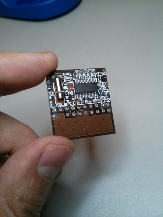
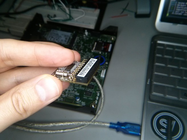
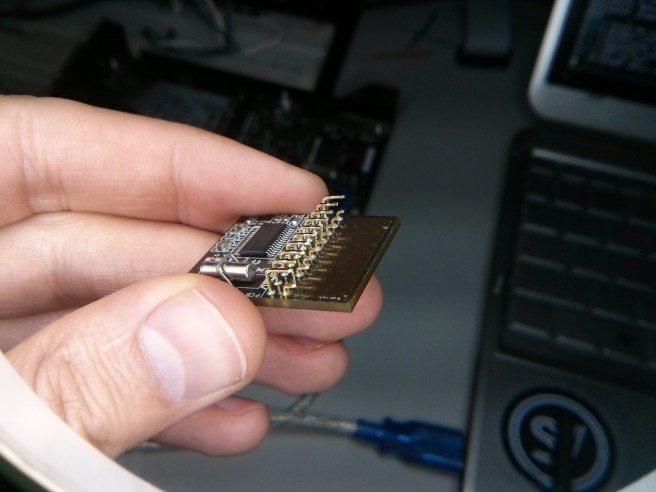
To start out you’ll need a TPM and one designed to attach to your system on the LPC bus. TPMs are a PITA to buy really. There are 3 main companies that manufacture them but you can’t buy them direct. Thankfully there are some motherboard manufacturers out there that support the TPM via a “daughter-card” and from my experience this is mostly the high end manufacturers like Asus and Supermicro. I had 2 Asus TPMs laying around so this seemed like a good opportunity to put them to use. On Amazon these TPMs go for about $15 but when I bought mine almost a year ago they were less than half that.

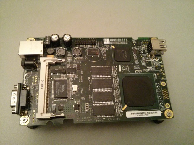
The system that started out trying to attach this thing to is an alix3d2. I also picked up one of the newer PCEngines APU but *spoiler alert* only after I had serious problems getting the alix to work.

You’ll also need a soldering iron and the usual soldering / prototyping gear on hand (lights, wire, solder, magnifying glass etc). That’s right I said soldering. It’s been a while for me too. Like 10 years. Don’t worry there isn’t much too this and it was really fun.

Prototyping

As you’ve likely guessed by now, just because a system has an LPC connector doesn’t mean this thing is plug and play. The Asus TPM daughter card has pin 4 blocked / keyed and the ALIX doesn’t so that’s our first hint. The real data is in the respective pin diagrams. Finding these isn’t as easy as I’d hoped so I had to do some digging.

The docs for the ALIX systems are all on the PCEngines website so that part’s easy. The Asus TPM doesn’t seem to have any docs though. If you take the time to dig into the boards that support them though you’ll find the manuals for these boards have the pin assignment documented. I pulled down the manual for the P9D-WS and used this as a reference. Page 2-29 has what we’re looking for.

Pin Layouts

With the pin layouts in hand we can see clearly that plugging the TPM daughter card directly into the board isn’t gonna happen. I’ll reproduce the layouts here so we can view them side by side:

Asus TPM PCEngines LPC
pin signal signal
1 PCICLK PCICLK</td
2 GND GND
3 FRAME LAD0
4 BLOCKED GND
5 PCIRST# LAD1
6 NC GND
7 LAD3 LAD2
8 LAD2 GND
9 +3V LAD3
10 LAD1 GND
11 LAD0 LFRAME#
12 GND GND
13 NC PCIRST#
14 NC CLK48A
15 +3VSB ISP
16 SERIRQ Vcc (+5V)
17 GND GND
18 CLKRUN V3
19 PWRDWN SERIRQ
20 NC LDRQ#

There’s basically no overlap in the pin layouts here except for a few ground connections. This blew my mind at first but after searching through the Intel Low Pin Count Interface Specification it turns out that this bus was intended for use on-board only and so there’s no pin layout specified for external connectors. First mystery solved. Now let’s figure out how we’re gonna wire this thing up.

To the breadboard!

This isn’t going to be as easy as “plug and play” but it’s not far off. We just need to connect the right pins. With the pin map above and a little help from the spec (to get the minimum required connections) we can pull out our breadboard and prototype this thing.

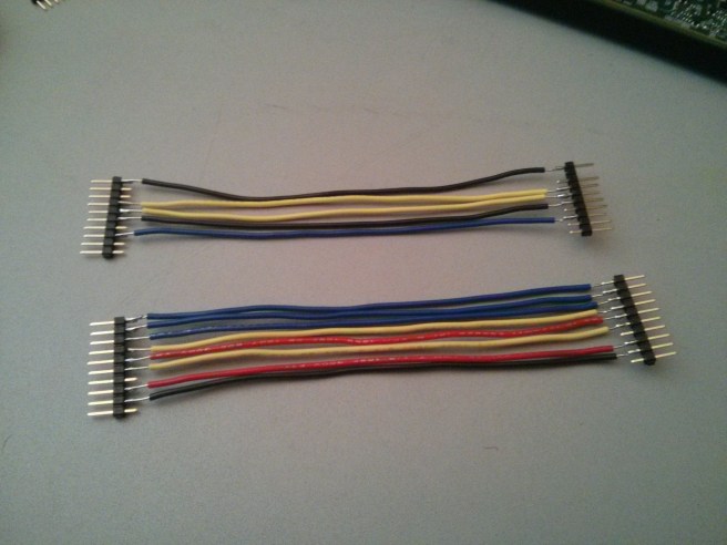
If you’re like me you’ll have to go out and buy materials as you need them. Luckily I live minutes away from HSC Electronic Supply which is an amazing surplus electronic shop. After an hour or 3 poking around the piles of old electronic gear I managed to scrounge up a 20 pin ribbon cable with a connector that looked like it might fit on my breadboard. With a 20 pin DIP ribbon cable connector I had what I needed to connect the alix to the breadboard.

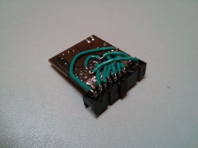
Next was to get the TPM daughter card wired up to the breadboard. This was harder than I expected. I couldn’t easily find a connector that would suit this purpose that didn’t require waiting for shipping. So I soldered some wires up to breakaway headers and rigged up a horrible TPM-to-breadboard connector. Then we just hook up the two using the following mapping:

TPM ALIX Signal
1 1 PCICLK / LCLK: 33MHz clock
3 11 LFRAME#: Transaction signal
5 13 LRESET#: Bus reset. AKA PCIRST#
7 9 LAD3: Data lane
8 7 LAD2: Data lane
9 & 15 18 3 Volts DC
10 5 LAD1: Data lane
11 3 LAD0: Data lane</td
16 19 SERIRQ: Serialized interrupt signal

After some fiddling (kicking, screaming and burning myself with a soldering iron) this is what it looked like:

IMG_20150213_093921

IMG_20150212_175548
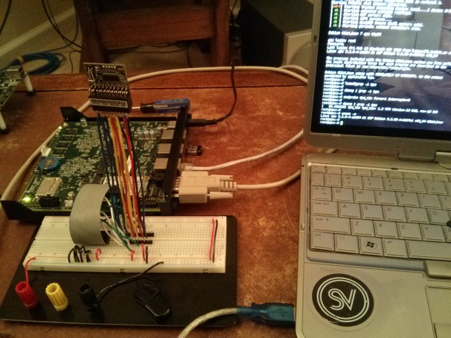
Now it SHOULD have worked. These are the right connections. But on the alix3d2 I got no love. I didn’t actually get this set-up to work till my apu1d showed up in the mail 3 days later. For whatever reason the external LPC on the alix3d2 just doesn’t work as advertised. Without an oscilloscope I can’t debug much beyond whether the voltage and ground pins are OK (and they are) so for now that will remain a mystery. So the alix3d2 is out and the apu1d is in.

Anyways we can do better than this bootleg breadboard setup. Let’s see about cleaning it up.

IMG_20150213_093453
IMG_20150213_093638

Clean it up

The wiring above was super flaky and that shouldn’t be a surprise. I didn’t get the length of each wire exact and the pins slipped around a bit in the plastic. I ordered some IDC breakout helpers from Adafruit but they were garbage. They plug into the breadboard fine but the pins aren’t long enough and they just pop back out immediately.

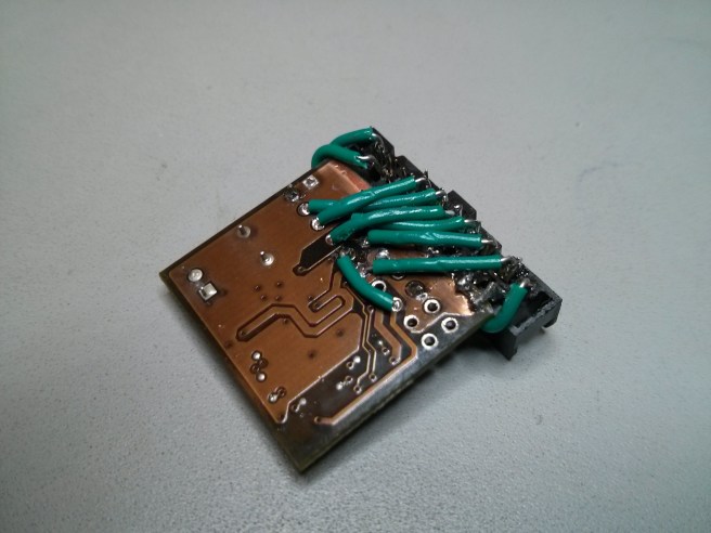
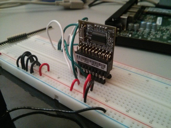
So again I hacked up another connector out of DIP/DIL headers and some breakaway headers spaced to span the gap in the breadboard. This is generally a bad idea since the solder is what’s holding the whole thing together but it worked out pretty OK:

IMG_20150213_151417

IMG_20150216_183250

IMG_20150214_134235

Packaging for the APU enclosure

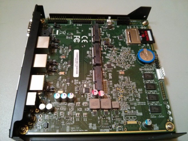
After convincing ourselves that the wiring above is right on the breadboard we need to clean this up so that it fits in the enclosure with the APU. There’s not a lot of space in the PCEngines recommended case1d2 but there’s enough if we’re sufficiently inventive. And by “inventive” I mean “you’ve got a hacksaw”.

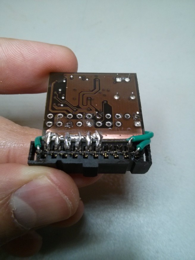
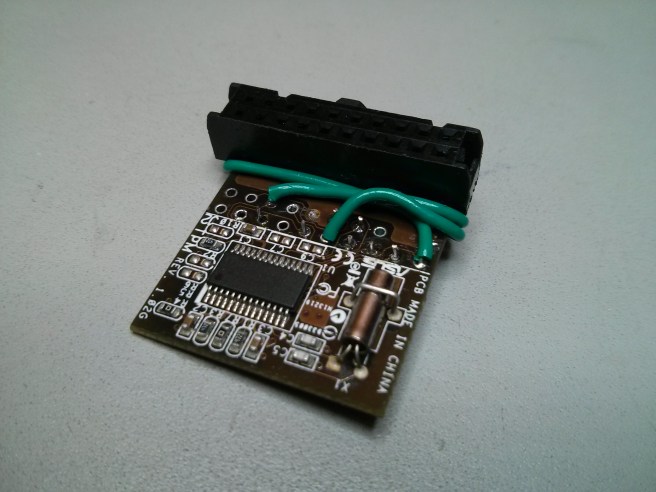
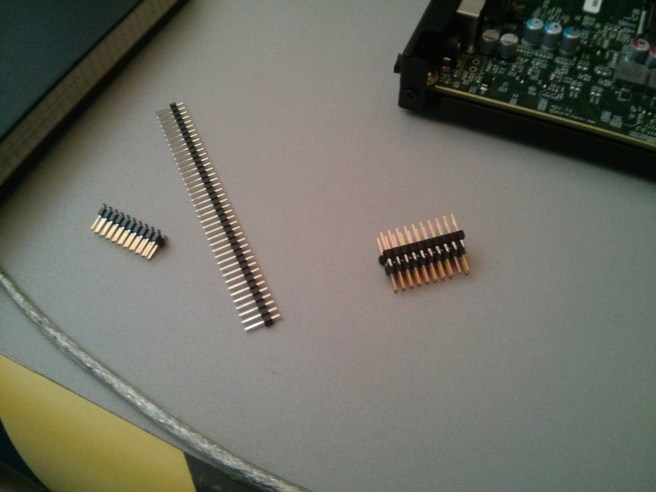
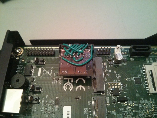
Start out by removing the female header from the TPM and trim back the connector pins. If we flip this header on it’s side we can use it to mount the TPM once we reconnect it. This would require either unblocking pin 4 on the connector or cutting pin 4 off of the APU board. Since pin 4 on the APU is ground anyways this shouldn’t be a problem.

I used a 20 pin DIP to ribbon cable connector for my setup. I sanded down the daughter board to expose the copper on the base which happens to be ground and connected this with the even pins on the connector up through 12. This proved to be a pretty solid base as it holds the daughter board nice and tight to the connector.

Then we just cut wires and solder pins per the table above. The wire I had on hand was 28 gauge which was a bit too big and the soldering job is straight up ugly in spots but it’s the first bit of soldering I’ve done in 10 years so that’s good enough for me. I’ve got another TPM on hand so I’ll have another go now that I’ve had some practice.

Testing

I used both a Debian install with the tpm-tools package to test this as well as the core-image-tpm from meta-measured. I’d recommend sticking with Debian unless you feel like falling down the rabbit hole of an OE build. The important thing to keep in mind is that the APU BIOS doesn’t support the TPM so it won’t do the necessary setup for us.

The BIOS is supposed to do a number of things to set things up so that the OS can use the TPM. This includes running the TPM self test, enabling it and setting up ACPI entries to make it easy for the OS to talk to it. With the stock BIOS on the APU we won’t get any of this. Thankfully the number of platforms that have implemented TPM support wrong in the BIOS over the years is quite high so the Linux TPM TIS driver can do all of this for us if we give it the right parameters:

root@apu:~# modprobe tpm_tis force=1
[   74.027383] tpm_tis tpm_tis: 1.2 TPM (device-id 0xB, rev-id 16)
[   74.063388] tpm_tis tpm_tis: Issuing TPM_STARTUP
[   74.260392] tpm_tis tpm_tis: TPM is disabled/deactivated (0x7)
[   74.308465] genirq: Flags mismatch irq 4. 00000080 (tpm0) vs. 00000000 (serial)
[   74.315956] tpm_tis tpm_tis: Unable to request irq: 4 for probe
[   74.436459] genirq: Flags mismatch irq 8. 00000080 (tpm0) vs. 00000000 (rtc0)
[   74.443753] tpm_tis tpm_tis: Unable to request irq: 8 for probe

The modinfo command will tell you all of the gory details about what these parameters do if you’re interested. The short version is that force=1 causes the driver to ignore ACPI and probe for the TPM device. You can also add the interrupts=0 argument to disables interrupts which will get rid of all of the genirq errors. After this you should see /dev/tpm0 appear magically. You can then start tcsd and get some version info out of the TPM:

root@apu:~# tpm_version 
  TPM 1.2 Version Info:
  Chip Version:        1.2.3.19
  Spec Level:          2
  Errata Revision:     2
  TPM Vendor ID:       IFX
  Vendor Specific data: 0313000b 00
  TPM Version:         01010000
  Manufacturer Info:   49465800

You won’t be able to do much more than this though since the BIOS hasn’t enabled the TPM for us. We’ll get past this in my next post.

Atom Based Home NFS

It’s been a while since I’ve posted any new content but that’s not because I haven’t been doing anything worthy of mention. During the few breaks I’ve had from my day job I took the time to replace my QNAP 419p NAS with a custom system to host NFS shares. Here’s just a quick laundry list of the parts I settled on after quite a bit of shopping.

My requirements for this system were really basic. All it does is host NFS shares and run rTorrent from time to time. There was no need to use a full desktop grade processor but I still wanted something x86 compatible with a good bit of ram and a PCI-E port so I could use a real hardware RAID card.

Motherboard

The Super Micro MBD-X7SPE-HF-D525 was a good fit. It has a sweet little Atom D525 soldered on to the board and it’s surprisingly quick (1.8GHz) though it’s no work horse. There’s only one 16x PCI-E port but that’s all I need. It supports up to 4G of ram though it’s pretty low end laptop memory. It also has two NICs so you can bond them for more throughput if you want to get fancy.

If you check out the Super Micro site you’ll see they advertise this board as having RAID on board. It’s still not hardware RAID though and since the RAID is done in firmware / driver the Atom processor on this board would have a very hard time keeping up with parity calculations under heavy usage. There’s plenty of literature out there about “fake RAID” so don’t be fooled.

RAID Card

I’ve had excellent luck with 3ware in the past so when they were bought out by LSI I was skeptical. Some of their older cards are still branded 3ware and I tracked down a 3ware 9650SE 8LPML on ebay for under 300 … since I couldn’t afford it new at close to $500 when I was looking 3 months back.

The Linux drivers for this card and the management software are still great. Setting up RAID 6 was easy though the card requires 5 drives to do this RAID level where theoretically it should only need 4.

RAM

The memory for the Super Micro board is practically free. I tracked down two 2G SODIMMs of Kingston ValueRAM for like $30. Not the fastest ram in the world but it works.

Disks

Buying 5 hard disks is not cheep. This is especially true if you want to get big drives and ones that will be fast enough to last. I went with 5 Western Digital AV-GP WD20EURS 2TB 3.0Gb/s drives. They’re nice and big, pretty fast and quiet. User reviews on sites like Newegg are a good way to check up on products before you buy. This one had particularly good reviews and so far they’ve been great. None were DOA as drives have a tendency to do. They’re also very quiet and run relatively cool.

Drive Enclosure

With this many drives it’s worth investing in an enclosure to hold them. You won’t have to rig fans on the drives to keep air moving over them and you’ll have the luxury of easy swapping if it something goes wrong and you need to swap out drives. There isn’t much available in this space so your choices are limited. I went with 2x ICY DOCK MB453SPF-B 3 in 2 enclosures.

I was a bit pissed when one of the enclosures showed up DOA but Newegg was pretty good about doing a quick exchange. It cost me a few extra bucks in shipping but it could have been worse … ::shrug::

Case

I had an old case from Lian Li and a small power supply that have been sitting in my basement unused for several years. Luckily the case it had the 4 5.25 bays that I need to hold these enclosures. Fitting enclosures into cases never goes as planned though.

The case is super nice but it had these little tabs that stuck out into the drive bays. These were intended to support individual 5.25 drives but they just got in the way of these enclosures. They were easy enough to remove with a saw and a file.

That’s about all there is to it. Setting up the RAID so I could boot Linux from the 3ware card was a bit of a pain and I wish I had documented the process. Setting it up through the firmware interface took some experimentation but it is possible. Then just install Debian and an NFS server and you’re done.

Thruxton 900 Ceramic Exhaust

It’s a new year. I’m not one for resolutions but something I always aim to do is put up more info on the mods I’ve made to my 2004 Thruxton 900. Last time I posted it was about the chrome T100 engine covers I picked up. In those photos the exhaust was off because it was away getting a ceramic coat from a local guy a buddy of mine recommended. As promised (if a bit late) here are the photos of his work:

The contrast between the two photos above is pretty dramatic. They look even better on the bike:

The exhaust clamp covers had some large blemishes when I picked them up. The guy at Affordable Powder Coating in Cato N.Y. was cool and fixed ’em up for me without any hassle.

I’m very happy with the way this turned out. It didn’t cost much and the pipes run super cool too. After running for nearly an hour I can stop and touch the tail of the muffler and it’s almost cool enough to hold on. I wish I had a dyno run from before and after so I could be sure of the horse power difference but I can really feel it.

So this isn’t much of a DIY post since removing and replacing the exhaust is just a few bolts and a little grease. Helps to have an extra set of hands to fit the pipes through the frame too. The photos sure are nice though … they’ve got me longing for riding weather in a bad way.

madwifi on lenny router

For the past two months my day job has taken over my life. As always, during the height of my insane work schedule my wireless router started acting up. I guess I needed something to break so I had an excuse to take a much needed break from work. I’d pretty much forgotten I even had a wireless access point because it had been so long since it required any attention. I learned a few things that are even worth mentioning here in the process

First off the router I had to fix wasn’t an off-the-shelf 802.11 box. It was actually my first PC Engines router built on the old wrap1e103. It ran Debian Sarge and had an Atheros AR5413 802.11abg which was hot shit when I bought it.

Needless to say there wasn’t any reason to try to fix this system. It’s old, tired and wasn’t experiencing any specific problems except running really slow every once in a while. Best bet was to upgrade.

Almost a year ago I blogged about a VPN gateway that I built on a new PCEngines ALIX platform. I drafted that system to replace this dying Sarge box. Upgrading to Lenny and faster hardware was long over due. It wasn’t all smooth sailing though.

Turns out the madwifi drivers are in flux and the drivers available on Lenny are pretty unstable. Luckily a little Googling turned up someone who already did the research for me and solved this problem! Their fix did the trick and likely saved me a full night of scouring the interwebs. Following these directions the madwifi drivers came up fine in hostap mode and were offering DNS and DHCP through dnsmasq within minutes.

I even had enough time left over to set up the VPN so I can login to my home network while I’m on the road. Since I’ve been traveling every other week all summer this is going to come in handy. The iptables rules for this got pretty interesting so I’ll probably post something about that in the near future.

T100 Engine Covers

In my first two years riding my motorcycle I learned a few things the hard way. Long story short I laid my Thruxton down twice, once on each side. They weren’t bad spills but I got a few cool scars out of the deal and so did my bike.

A few weeks ago I purchased new T100 (chrome!) engine covers and today I’m fixing up the last of the damage left over from my wipe-outs. The alternator cover isn’t too bad but the primary got beat up something aweful. Here’s what my covers looked like before:

Removing Old Engine Covers

The first and most obvious step is draining your oil. The primary and alternator covers are wet seals and if you break them you’re gonna leak all of your oil out on to your driveway / garage floor. I’ve planned this maintenance around an oil change anyway so I drained my oil completely and have a new oil filter ready to go.

I started on my primary cover: removed the bolts and started to pull. This thing wasn’t budging so I broke out my rubber mallet. That’s right, when all else fails hit it with a hammer … but not one that will scratch up your new chrome parts! A few good taps around the seams and the seal gave and started dripping oil all over the place. Have a pan ready and set yourself up on some cardboard to catch any stray drips.

The cover should come off easy enough but the seal is likely to break up leaving bits stuck around the edges. You’ve got to get all of this off before you can put the new cover and seal on so break out a razor and carefully scrape what’s left of the old seal off the engine. Be very careful not to get little bits of the seal on any of your engine’s internals. You do not want little bits of plastic floating around gumming up the works.

When you’re done the mounting surface on the engine should look nice and clean. Here’s what the primary side looks like (forgot to shoot the alternator side):

Alternator Cover

On the alternator side you’ll notice some wires that run out from between the engine case and the cover. These connect to the stator and power your electrical. The seals around these are a bit of a pain. You’ll have to transfer the coils to you new cover then worry about the wires.

When you reattach the alternator cover you’ll have to get your new seal in place but that probably won’t be enough. The wires have a rubber housing that you should seal up too. I opted to “borrow” some Form-A Gasket Sealant from my room mate.

This stuff is nasty. Get ready to apply it with your fingers and then spend some time scrubbing it off your hands later. You want to put enough on to fill the cracks but if you put so much on that it oozes out. It’s probably oozing out inside the case too which is not a good thing.

When you’ putting the the cover back on you’ll wish you had a few extra hands. Holding the seal, the wires and the cover in place at the same time is a pain, especially with the seal goop getting on everything. Once you juggle it all into place torque down the bolts to the spec (9Nm if I remember correctly which isn’t much).

The sprocket cover is easy in comparison. No seals no nothing. Just throw it on. Here’s what they look like, nice and shiny:

Primary Cover

The primary side doesn’t have any wires for you to worry about but it’s more of a pain. First off if you’re bike is on it’s kick stand the primary side will be tilted toward the ground which will make putting the cover back on much more difficult. Specifically there are a few metal pins that are seated in the cover and they’ll slide out much more easily if the engine is tilted downward.

Pay attention to the small cog at the lower front of the engine on this side. There’s a funny washer sitting over the pin holding it in place. This pin has a corresponding hole it will fit into on the inside of the primary cover. If you’re not careful while the cover is off this washer and pin may slip out. Be very careful of this.

Also on the primary side is the clutch leaver that you’ll have to transfer from your old cover to the new one. These are held in place by 7 or 8 hex screws that Triumph was kind enough to goop up with red locktite. This makes removing them very difficult and you’ve got to be extra careful to keep from stripping them.

I’ll admit that I stripped one but managed to get it out still. I had to take a trip to the local fastener shop in Syracuse to get a replacement. As much as the locktite is a pain when you’re removing the bolts it’s a good idea to use some when you put them in your new cover. Having one of these come loose in your engine would pretty much be the end of it.

I probably don’t have to say this but when you do transfer the clutch leaver over keep an eye on the set-up in the old cover and make sure you get everything in place right. It’s not hard but I’m sure it can be screwed up if you’re not careful. Be sure to keep track of the pin seated in the case that actuates the clutch. Mine kept dropping out of place when I was putting the cover back on.

Speaking of putting the primary cover back on, it’s a pain in the ass! If you’ve got an extra set of hands around you’re gonna need them. Here’s what it should look like when you’re done.

Oil and a Paryer

So when both covers are back on with the seals in place and torqued down, finish your oil change (change your filter etc). It’s not uncommon for the seals to leak a little bit at first until their seated. If they keep leaking after you’ve had the engine running for a bit try tightening down the bolts a little more but not too much. If this doesn’t fix your leak then something more serious went wrong (damaged seal?).

If you were looking at the pictures closely you’ll notice there weren’t any pipes on my Thruxton. I timed changing the engine covers with sending my pipes out to a local guy who runs a paint booth / powder coating shop out of his garage. More to come on that.

Thruxton Sprockets

The chain on my Thruxton was about 6 years old and looking pretty ratty so I decided it was time for a new one. My buddy recently did some homework on chains and he ended up buying an EK X Ring chain so I followed suit. After hitting my Haynes manual to find out the right specs (525, 104 links) I picked one up. Found a good deal on an EK MVXZ 525 through ebay along with a chain tool to break the old one, and get the new one on.

Old Chain

My first mistake was trying to break the old chain off of my Thruxton with a $20 chain tool and not enough of the rivet ground down. So I broke the pin on that one and, surprise, it didn’t come with a spare. I took a pretty good chunk out of my knuckle when the pin broke and I was a bit pissed so I switched over to the cutting wheel and just cut the chain off. Should have just done that in the first place. Glad to have the old chain off too since it had a few links that weren’t flexing right. That’s why it felt funny while I was riding.

Since I was without a chain tool now I took the new one down to Destiny Motorsports and Garry cut it down for me. Great spot if you’re in Syracuse and you need an inspection or service. They’ve always done right by me and this time was no different.

Rear Sprocket

Now that I had the new chain at the right length I had to switch out the sprockets. I figured since I had the chain off it would make sense to upgrade the sprockets with some after market ones from British Customs. I picked up an aluminum rear sprocket and a fancy steel front too. I didn’t change the tooth ratio but I’m tempted to try a smaller front sprocket in the future.

Anyways getting the rear sprocket off was easy enough. Remove the rear wheel, pull the old one, put on the new one. The white stuff on the new sprocket is just lithium grease from the new chain. They come covered in that stuff and you’re gonna want to wipe as much of it off the chain before you ride on it.

Front Sprocket

Getting the front sprocket off was a bit of a trick. First off you’ve gotta bend back a huge washer that is bent down on the nut that holds the sprocket on. I did it with a screw driver but I’m sure there are better ways. This nut is huge by the way. 36 or 38mm and sockets that big get super pricey, not to mention a driver for it and a torque wrench if you want to torque it back down to spec.

After putting the new sprocket on you’ve gotta torque down the nut and flatten out the washer again. Flattening the washer down on the sprocket isn’t something you can do with a screwdriver. A small punch works perfectly if you’ve got one laying around.

New Chain

Pressing the master link on the new chain on is a real pain. I’ve already gone through one cheep chain tool so this time I got the real deal from EK. This tool is worth every penny and makes getting the master link on much easier than it would be normally. They’ve still got the EK chain tool on special at Moto-Chains so if you’re gonna buy one I’d recommend this one. It’ll press on the plates and press out pins. You can even use it for riveting.

So this is what the master link looks like after it’s been riveted. I didn’t take a picture of the chain when it was completely new. The photo below is the chain after 1200 miles through the white mountains. I was rushing to get the new chain on for the trip and forgot to snap a photo when it was fresh.

So that’s it. The new chain and sprockets are great. Not something you really notice when you’re riding but that’s the whole point. My old chain had a few links that weren’t flexing right and I could definitely feel the kinks when I was riding on it. This new one is super smooth which is the effect I was going for.

Chrome Valve Cover

A few weeks ago the seal on my valve cover started leaking a bit of oil. It was very minor at first so I ignored it. Eventually it started leaking out on to my exhaust (headers) so I’d pull up to a light and notice a bit of smoke rising off my front end. That’s about the point when you can’t ignore the problem any more.

Replacing a seal is pretty easy especially a dry seal like the valve cover seal. I’ve been planning some upgrades though so I took the opportunity to blow some money. There’s some back story here though: this was my first bike and I learned to ride on it, the hard way. In my first summer I laid it down once on each side. The bike survived with minimal damage but the engine cover on the clutch side looks like someone went at it with a file. The alternator and valve covers got off easy but still got chipped up. Over time the hard coat on them started cracking noticeably.

Since I had to remove the valve cover I might as well replace it, right? Might as well get a chrome one too 🙂 I even managed to track down the chrome replacement on ebay for pretty cheep so that’s always nice. Now I really screwed this one up though: I didn’t take as many pictures as I should have. With that in mind here’s the before shots with the tank removed.

When the valve cover is off the cam shafts are exposed. It was all I could do to keep from grabbing my laptop and ordering some more aggressive replacement cams. One step at a time. First replace the seal which actually wasn’t in bad shape. It was a bit frayed at the edges but there wasn’t any serious wear that I could see.

This is the point where I got excited, threw the camera to the side, replaced the seal and threw the new cover on without taking any pictures. I’ll learn eventually. I did it by the book (well by the Haynes Manual). I put a bit of grease on the seal, fitted it into the cover and replaced the bolts at the specified torque. Here’s what it looked like after it’s all back together.

Sadly it’s still bleeding a bit of oil. Nothing as bad as it was so I’m thinking the gasket may just need to get seated. Also the grease I applied may be running out a bit. For now I’m just carrying a shop rag with me and hoping for the best.

I ordered the rest of the replacement covers in chrome from British Customs along with a bunch of other stuff. My next post largely depends on what arrives in the mail first.