TPM2 UEFI Measurements and Event Log

UPDATE: I’ve continued this work as “pure” UEFI shell executables and so some of the links to this work with Grub2 have gone dead. The updated version of this work can be found here: https://twobit.org/2019/05/21/uefi-tpm2-examples/. Work to integrate these tools into Grub2 is still on-going.

Has it really been over 6 months since I last wrote something on the blog? Crap. The standard excuses apply: busy busy busy. I got sucked into the OSS TPM2 software stack project @ Intel in a huge way.

I screwed up something fundamental along the way though: I moved on to this new project before finishing off an older project. So I’m here to set things right. The OpenXT summit is in a week so I’m cleaning out my backlog and it’s time to write up the stuff I was working on back before I fell down the TPM2 TSS hole. Come to think of it I’ve got some interesting stuff to write about the TPM2 TSS work but first things first: TPM2 in EFI and Grub2.

This is likely the first post in what will become a series on the subject. I’ll try to keep this post to an overview of the TPM2 EFI protocol, the basics of what I’ve been adding to grub and I’ll do a slightly deeper dive in to the pre-boot TPM2 event log that’s maintained by the TPM2 EFI driver / firmware. Future posts will pick up the remaining bits and get into the details of how this was integrated into meta-measured.

TPM2 UEFI recap

I left off my last post describing some oddities I ran into in the TCG TPM 2.0 EFI Protocol specification. With that issue out of the way I spent some time playing around with the functions exposed by the protocol (in the UEFI sense) and what they would allow us to do in the pre-boot environment. Naturally there’s a purpose here: measuring stuff.

Before we get too far into the post here’s a pointer to the code I’ve been developing: . It’s been a few months since I seriously slowed down work on this to focus on the TSS for Linux but I intend to revive it so that I can finish it off in the near future. Intel has already demonstrated this code @ the TCG event @ RSA 2016 so it’s functional but still just ‘demo quality’.

The Protocol

The stuff we want to measure here is the code and the data that was run as part of booting our system. In this case we want to extend the measurement chain from the firmware up through Grub2 to the OS. Despite past efforts on a Grub2 fork known as “trusted grub” the majority of Linux systems have a gap between measurements taken by the firmware and measurements that are taken by kernel or user space code.

In our efforts to fill this gap, let’s start by taking a quick look at the functions that are exposed by the TPM2 UEFI protocol. In UEFI the concept of a ‘protocol’ isn’t what I typically think of when I hear the word. When I hear ‘protocol’ the first thing that comes to mind is a network protocol like TCP or IP. In the context of UEFI it’s a bit different: it defines the interface between UEFI applications and some set of services offered by the UEFI runtime.

The interaction model is very basic: You provide the UEFI runtime with a UUID identifying the protocol you want to use and it will return to you a structure. This structure is protocol specific and it’s effectively a table of function pointers. For the TPM2 there’s 7 commands and thus 7 entries in this structure, one for each function.

The TPM2 EFI Protocol Specification documents this structure and the functions it exposes in section 6. My implementation pulls the structure directly from the spec as follows:

typedef struct tdEFI_TCG2_PROTOCOL {
  EFI_TCG2_GET_CAPABILITY                      GetCapability;
  EFI_TCG2_GET_EVENT_LOG                       GetEventLog;
  EFI_TCG2_HASH_LOG_EXTEND_EVENT               HashLogExtendEvent;
  EFI_TCG2_SUBMIT_COMMAND                      SubmitCommand;
  EFI_TCG2_GET_ACTIVE_PCR_BANKS                GetActivePcrBanks;
  EFI_TCG2_SET_ACTIVE_PCR_BANKS                SetActivePcrBanks;
  EFI_TCG2_GET_RESULT_OF_SET_ACTIVE_PCR_BANKS  GetResultOfSetActivePcrBanks;
} GRUB_PACKED EFI_TCG2_PROTOCOL;

Each of these types is a function with a prototype / parameters etc just like any other function in C. The spec has all of the gory details, including the updated data about the unpacked structure returned by GetCapability. But given our stated goals above: measuring stuff, we really need just one command: HashLogExtendEvent.

This is probably a good time to reflect on how great UEFI is. In the PC BIOS world we would be writing assembly code to interact with the TPM using memory mapped IO or something. In UEFI we call a function to get a table of pointers to other functions and we then call one of these functions. All of this can be done in C. Pretty great IMHO. And if you’re working in the Grub2 environment Grub already has wrappers for invoking the UEFI command to get access to the protocol structure and to invoke functions from it.

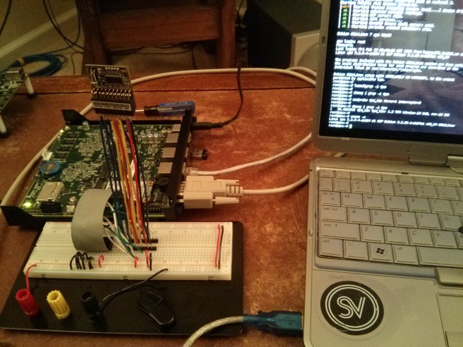
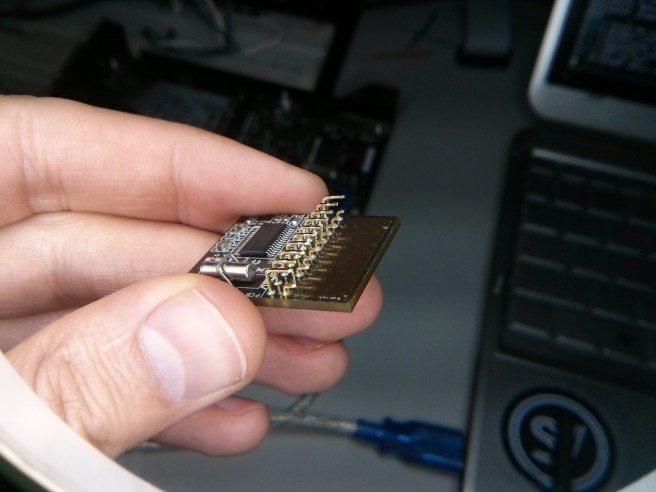
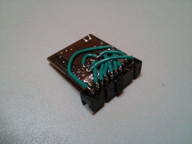
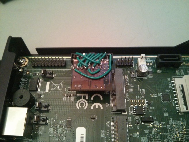
On my Minnowboard Max (MBM) this is pretty easy. Add an FTDI serial cable (the one on sparkfun is way over priced but really nice) and you don’t even need a monitor. Anyways, back to it.

HashLogExtendEvent

The TPM is a pretty complicated little thing but it’s fundamental function: extending data into PCRs, is pretty simple. All you need is a buffer holding data, the size of the buffer, and a data structure describing the extend event. This last bit of data is used by the UEFI firmware to update the log of extend events (aka: “stuff we’ve measured”).

In my grub code I’ve broken this down into two functions. The first is a thin wrapper over the HashLogExtendEvent function that takes the data buffer,size and EFI_TCG2_EVENT structure as a parameter. The second is more of a convenience function that builds up the EFI_TCG2_EVENT structure for the caller using “standard” values. The two prototypes are as follows:

grub_err_t
grub_tpm2_extend (EFI_TCG2_PROTOCOL *tpm2_prot,
                  grub_efi_uint64_t  flags,
                  char              *data,
                  grub_efi_uint64_t  data_size,
                  EFI_TCG2_EVENT    *event)
grub_err_t
grub_tpm2_extend_buf (grub_uint8_t      *buf,
                      grub_efi_uint64_t  buf_len,
                      const char        *desc,
                      grub_uint32_t      pcr)

The EFI_TCG2_EVENT structure is pretty simple but it’s annoying to calculate the size values for each call so the convenience function is a good way to keep code sizes manageable. Take a look at the code here if you’re interested in the details.

When Grub does something like load a module of code, or a command from a config file or a kernel / initrd image we measure it into a TPM PCR using the grub_tpm2_extend_buf function providing it the data to hash, the length of the memory buffer holding said data, a brief description of the event (like “linux kernel” or “loadable module”) and the PCR we want to extend with the measurement.

Probably worth noting is that the current implementation uses the string obtained from the grub.cfg file in the Event field. For now this is a debugging mechanism. For a deployed implementation taking input directly from the user (the grub.cfg file should be considered as such) is pretty risky. Instead it’s probably better to use a generic string that describes what the input data is, but doesn’t contain the data directly.

TPM2 Preboot Event Log

It’s very difficult to extract meaning from the contents of a TPMs PCR. Up till now we’ve covered the bits necessary to extend data into a PCR from within Grub. We can extend value after value into it and at some time in the future read it back. But when someone looks at the value they’ll likely want to recreate it to verify every component that went into generating the final value. The name of the UEFI protocol function that extends a value into the PCR is particularly descriptive because, like it says, it also updates the preboot measurement log. This log is where we go to get the data we need to understand our PCR values.

Being able to parse this log and view the contents is also an integral part of verifying or debugging the work I’ve been doing. In this vein, after I managed to get a call to extend a value into a PCR doing more than returning an error code (yeah it happens a lot to me for some reason) I immediately wrote a bit of code to parse and dump / “prettyprint” the audit log.

Grub has a built in shell and an interface to load code modules and commands. This seemed like the “right” mechanism to load commands that I could execute on demand. If you boot grub without a config file you’ll land immediately at the shell and so I found myself debugging by running grub and then executing commands to extend arbitrary data into the log and then parsing the log and dumping it to the console output. If you’ve got a serial console hooked up you can capture this output using minicom or whatever. The commands that parse the log can be found in a module I’m calling tpm2cmd until I come up with a better name. This module has a few commands in it but to dump the event log the tpm2dumplog command is what you’ll need.

The code that walks through the event log data structure is pretty boring. It’s tightly packed so there’s a bit of work to be done in calculating offsets but it’s not rocket surgery. The interesting part is in interpreting the log and figuring out what to do with the data.

Let’s capture an audit log using these new commands. First we need to be able to boot grub and get to the grub shell. I’ve been integrating this work into the meta-measured OpenEmbedded meta-layer so if you want to see this at work you can build the core-image-tpm image or download one from my meta-measured autobuilder. If you want to build Grub by hand and install it on a thumb drive the results should be the same. Just grab the code from my github. I won’t cover the details for this here though.

Assuming you’ve got the latest core-image-tpm image from meta-measured built, just dd the ISO on to a thumb drive and boot it (on a UEFI system with a TPM2 of course). If you’re grabbing the ISO from my autobuilder the target MACHINE is an MBM running the 32bit firmware so YMMV on any other platform. When you finally get to the grub menu hit ‘c’ to get a shell. From here the tpm2cmd module provides a few functions (tpm2dumpcaps tpm2dumplog and tpm2extend) that you can execute to play around. But before we get too far into that it’s important to note that the firmware can support either the new TPM2 event log format or the old TPM 1.2 format. The capabilities structure will tell you which your firmware supports. On the Minnowboard Max I only get the 1.2 foramt:

grub> tpm2dumpcaps
TPM2 Capabilities:
  Size: 0x1c
  StructureVersion:
    Major: 0x01
    Minor: 0x00
  ProtocolVersion:
    Major: 0x01
    Minor: 0x00
  HashAlgorithmBitmap: 0x00000003
    EFI_TCG2_BOOT_HASH_ALG_SHA1: true
    EFI_TCG2_BOOT_HASH_ALG_SHA256: true
    EFI_TCG2_BOOT_HASH_ALG_SHA384: false
    EFI_TCG2_BOOT_HASH_ALG_SHA512: false
    EFI_TCG2_BOOT_HASH_ALG_SM3_256: false
  SupportedEventLogs: 0x00000001
    EFI_TCG2_EVENT_LOG_FORMAT_TCG_1_2: true
    EFI_TCG2_EVENT_LOG_FORMAT_TCG_2: false
  TPMPresentFlag: 0x01 : true
  MaxCommandSize: 0x0f80
  MaxResponseSize: 0x0f80
  ManufacturerID: 0x494e5443
  NumberOfPcrBanks: 0x00000000
  ActivePcrBanks: 0x00000000

The tpm2dumplog function is smart enough to check this structure before walking the log. It will prefer the TPM2 event log format if both are supported. There’s even a --format option so you can select which you want if both are supported but I haven’t had a chance to test this since I’ve not yet found a system with firmware supporting the 2.0 format. Booting straight into the grub shell and executing the tpm2dumplog command produces the log file below. Let’s pick a few example entries and see if we can figure out what they mean.

grub> tpm2
Possible commands are:

 tpm2dumpcaps tpm2dumplog tpm2extend tpm2sendlog
grub> tpm2dump
Possible commands are:

 tpm2dumpcaps tpm2dumplog
grub> tpm2dumplog 
TPM2 EventLog
  start: 0x79373000
  end: 0x79373c98
  truncated: false
prettyprint_tpm12_event at: 0x79373000
  PCRIndex: 0
  EventType: EV_S_CRTM_VERSION (0x00000008)
  digest: 1489f923c4dca729178b3e3233458550d8dddf29
  EventSize: 2
  Event: 
prettyprint_tpm12_event at: 0x79373022
  PCRIndex: 0
  EventType: EV_EFI_PLATFORM_FIRMWARE_BLOB (0x80000008)
  digest: 76bd373351e3531ae3e2257e0b07951a2f61ae42
  EventSize: 16
  Event: 
prettyprint_tpm12_event at: 0x79373052
  PCRIndex: 0
  EventType: EV_EFI_PLATFORM_FIRMWARE_BLOB (0x80000008)
  digest: f46823e31fcb3059dbd9a69e5cc679a4465ea318
  EventSize: 16
  Event: 
prettyprint_tpm12_event at: 0x79373082
  PCRIndex: 0
  EventType: EV_EFI_PLATFORM_FIRMWARE_BLOB (0x80000008)
  digest: 87ce3bc3cd17fe797cc04d507c2f8f3b6c418552
  EventSize: 16
  Event: 
prettyprint_tpm12_event at: 0x793730b2
  PCRIndex: 0
  EventType: EV_EFI_PLATFORM_FIRMWARE_BLOB (0x80000008)
  digest: 8725eb98a49d6227459c6c90699c5187c5f11e16
  EventSize: 16
  Event: 
prettyprint_tpm12_event at: 0x793730e2
  PCRIndex: 7
  EventType: EV_EFI_VARIABLE_DRIVER_CONFIG (0x80000001)
  digest: 57cd4dc19442475aa82743484f3b1caa88e142b8
  EventSize: 53
  Event: a????
prettyprint_tpm12_event at: 0x79373137
  PCRIndex: 7
  EventType: EV_EFI_VARIABLE_DRIVER_CONFIG (0x80000001)
  digest: 9b1387306ebb7ff8e795e7be77563666bbf4516e
  EventSize: 36
  Event: a????
prettyprint_tpm12_event at: 0x7937317b
  PCRIndex: 7
  EventType: EV_EFI_VARIABLE_DRIVER_CONFIG (0x80000001)
  digest: 9afa86c507419b8570c62167cb9486d9fc809758
  EventSize: 38
  Event: a????
prettyprint_tpm12_event at: 0x793731c1
  PCRIndex: 7
  EventType: EV_EFI_VARIABLE_DRIVER_CONFIG (0x80000001)
  digest: 5bf8faa078d40ffbd03317c93398b01229a0e1e0
  EventSize: 36
  Event: ?:=?E????geo
prettyprint_tpm12_event at: 0x79373205
  PCRIndex: 7
  EventType: EV_EFI_VARIABLE_DRIVER_CONFIG (0x80000001)
  digest: 734424c9fe8fc71716c42096f4b74c88733b175e
  EventSize: 38
  Event: ?:=?E????geo
prettyprint_tpm12_event at: 0x7937324b
  PCRIndex: 7
  EventType: EV_SEPARATOR (0x00000004)
  digest: 9069ca78e7450a285173431b3e52c5c25299e473
  EventSize: 4
  Event: 
prettyprint_tpm12_event at: 0x7937326f
  PCRIndex: 1
  EventType: EV_EFI_HANDOFF_TABLES (0x80000009)
  digest: ed620fde0f449cec32fc0eaa040d04e1f1888b25
  EventSize: 24
  Event: 
prettyprint_tpm12_event at: 0x793732a7
  PCRIndex: 5
  EventType: EV_EFI_VARIABLE_BOOT (0x80000002)
  digest: aae4f77a57d91bf7beeee06e053a73eec78cc9ec
  EventSize: 62
  Event: a????
prettyprint_tpm12_event at: 0x79373305
  PCRIndex: 5
  EventType: EV_EFI_VARIABLE_BOOT (0x80000002)
  digest: d2ab4e0ed4185d5c846fb56980907a65aa8d3103
  EventSize: 168
  Event: a????
prettyprint_tpm12_event at: 0x793733cd
  PCRIndex: 5
  EventType: EV_EFI_VARIABLE_BOOT (0x80000002)
  digest: 7c7e40269acd5fb401b6f49034b46699bc5c5777
  EventSize: 136
  Event: a????
prettyprint_tpm12_event at: 0x79373475
  PCRIndex: 5
  EventType: EV_EFI_VARIABLE_BOOT (0x80000002)
  digest: abb0830c9bef09a2c108ceba8f0ff8438991b20a
  EventSize: 206
  Event: a????
prettyprint_tpm12_event at: 0x79373563
  PCRIndex: 5
  EventType: EV_EFI_VARIABLE_BOOT (0x80000002)
  digest: 79d23fb4ea34f740725783540657c37775fb83b0
  EventSize: 239
  Event: a????
prettyprint_tpm12_event at: 0x79373672
  PCRIndex: 5
  EventType: EV_EFI_VARIABLE_BOOT (0x80000002)
  digest: b8d59f3cde8b1fc5b89ff0b61f7096903734accb
  EventSize: 117
  Event: a????
prettyprint_tpm12_event at: 0x79373707
  PCRIndex: 5
  EventType: EV_EFI_VARIABLE_BOOT (0x80000002)
  digest: 22d22e14e623d1714cd605fef81e114ad8882d78
  EventSize: 121
  Event: a????
prettyprint_tpm12_event at: 0x793737a0
  PCRIndex: 5
  EventType: EV_EFI_ACTION (0x80000007)
  digest: cd0fdb4531a6ec41be2753ba042637d6e5f7f256
  EventSize: 40
  Event: Calling EFI Application from Boot Option
prettyprint_tpm12_event at: 0x793737e8
  PCRIndex: 0
  EventType: EV_SEPARATOR (0x00000004)
  digest: 9069ca78e7450a285173431b3e52c5c25299e473
  EventSize: 4
  Event: 
prettyprint_tpm12_event at: 0x7937380c
  PCRIndex: 1
  EventType: EV_SEPARATOR (0x00000004)
  digest: 9069ca78e7450a285173431b3e52c5c25299e473
  EventSize: 4
  Event: 
prettyprint_tpm12_event at: 0x79373830
  PCRIndex: 2
  EventType: EV_SEPARATOR (0x00000004)
  digest: 9069ca78e7450a285173431b3e52c5c25299e473
  EventSize: 4
  Event: 
prettyprint_tpm12_event at: 0x79373854
  PCRIndex: 3
  EventType: EV_SEPARATOR (0x00000004)
  digest: 9069ca78e7450a285173431b3e52c5c25299e473
  EventSize: 4
  Event: 
prettyprint_tpm12_event at: 0x79373878
  PCRIndex: 4
  EventType: EV_SEPARATOR (0x00000004)
  digest: 9069ca78e7450a285173431b3e52c5c25299e473
  EventSize: 4
  Event: 
prettyprint_tpm12_event at: 0x7937389c
  PCRIndex: 5
  EventType: EV_SEPARATOR (0x00000004)
  digest: 9069ca78e7450a285173431b3e52c5c25299e473
  EventSize: 4
  Event: 
prettyprint_tpm12_event at: 0x793738c0
  PCRIndex: 6
  EventType: EV_SEPARATOR (0x00000004)
  digest: 9069ca78e7450a285173431b3e52c5c25299e473
  EventSize: 4
  Event: 
prettyprint_tpm12_event at: 0x793738e4
  PCRIndex: 5
  EventType: EV_EFI_ACTION (0x80000007)
  digest: b6ae9742d3936a4291cfed8df775bc4657e368c0
  EventSize: 47
  Event: Returning from EFI Application from Boot Option
prettyprint_tpm12_event at: 0x79373933
  PCRIndex: 4
  EventType: EV_EFI_BOOT_SERVICES_APPLICATION (0x80000003)
  digest: 2d13d06efd0330decd93f992991b97218410688d
  EventSize: 64
  Event: ?kx
prettyprint_tpm12_event at: 0x79373993
  PCRIndex: 4
  EventType: EV_EFI_BOOT_SERVICES_APPLICATION (0x80000003)
  digest: e0fcc7f88f096737f8a95d7a86e7a4b33c365ebc
  EventSize: 145
  Event: Pqx
prettyprint_tpm12_event at: 0x79373a44
  PCRIndex: 9
  EventType: EV_IPL (0x0000000d)
  digest: 5c88780f029068d6f5863b943575556d7b98c558
  EventSize: 76
  Event: Grub2 command: serial --unit=0 --speed=115200 --word=8 --parity=no --stop=1
prettyprint_tpm12_event at: 0x79373ab0
  PCRIndex: 9
  EventType: EV_IPL (0x0000000d)
  digest: 392dc11bf1eea9e5e933e0e401fba80fda90f912
  EventSize: 28
  Event: Grub2 command: default=boot
prettyprint_tpm12_event at: 0x79373aec
  PCRIndex: 9
  EventType: EV_IPL (0x0000000d)
  digest: b993a2e236f21b72a05e401d241a5e7617367738
  EventSize: 26
  Event: Grub2 command: timeout=10
prettyprint_tpm12_event at: 0x79373b26
  PCRIndex: 9
  EventType: EV_IPL (0x0000000d)
  digest: f6afd73c21afe5a5136e7fdf7068d71fb4fc014b
  EventSize: 148
  Event: Grub2 command: menuentry boot {
linux /vmlinuz LABEL=boot root=/dev/ram0 console=ttyS0,115200 console=ttyPCH0,115200 console=tty0 
initrd /initrd
}
prettyprint_tpm12_event at: 0x79373bda
  PCRIndex: 9
  EventType: EV_IPL (0x0000000d)
  digest: 02775bb98cd27a98178eee72a1cd66bec285c839
  EventSize: 158
  Event: Grub2 command: menuentry install {
linux /vmlinuz LABEL=install-efi root=/dev/ram0 console=ttyS0,115200 console=ttyPCH0,115200
console=tty0 
initrd /initrd
}
prettyprint_tpm12_event at: 0x79373c98
  PCRIndex: 9
  EventType: EV_IPL (0x0000000d)
  digest: 69dd51ec4450a2e7b6f3da83370998908aa3370e
  EventSize: 27
  Event: Grub2 command: tpm2dumplog
grub>

The fields here are documented in the specification (version 1.22 of the TPM EFI Protocol spec this time though and in section 3.1.3) so I won’t cover them in detail. Instead let’s look at the first two events:

prettyprint_tpm12_event at: 0x79373000
  PCRIndex: 0
  EventType: EV_S_CRTM_VERSION (0x00000008)
  digest: 1489f923c4dca729178b3e3233458550d8dddf29
  EventSize: 2
  Event: 
prettyprint_tpm12_event at: 0x79373022
  PCRIndex: 0
  EventType: EV_EFI_PLATFORM_FIRMWARE_BLOB (0x80000008)
  digest: 76bd373351e3531ae3e2257e0b07951a2f61ae42
  EventSize: 16
  Event: 

Not a lot of data in these entries. Notably the ‘Event’ field is blank (this is where a textual description of the event should be). The first EventType is the telling bit though (that and that it’s the first thing measrued). This is the first measurement and thus the CRTM, well the CRTM version number at least? The second is much more generic: just some blob of firmware from the platform. What I do find puzzling though is that the first event is listed as 2 bytes long and the second as 16. This length is of the textual event data, the description that looks to be missing. What’s really happening here is that my code treats this field as a NULL terminated string, and the first byte is NULL so the code just doesn’t print anything. This is probably something worth investigating in the future (note to self).

This provides us with an interesting view of the boot process. Neither of these measurements (or the string of events that land in PCR[0]) have much meaning from this angle but the MBM firmware can be built from the EDK2 sources so it may be that with enough code reading we could divine where these values came from. The best thing we have to go on (without additional cooperation from the platform firmware provider) is the EventType and the PCR index where the data was extended. The TCG PC Client Platform Firmware Profile defines “PCR Usage” in section 2.2.4 and PCR[0] is for “SRTM, BIOS, Host Platform Extensions, Embedded Option ROMs and PI Drivers” so basically “firmware”.

For the code that measures the bits that grub loads and depends upon (modules and configuration data) we use PCRs 8 and 9. According to the PC Client PlatformPlatform Firmware Profile 8 and 9 are “Defined for use by the Static OS” which I guess includes the bootloader. According to convention (passed down to me by word of mouth) the even numbered PCRs are where binary data gets hashed and the odd PCRs are for configuration data. So I’m using PCR[8] for Grub modules and binary blobs (kernel, initrd) loaded by grub through the linux command. PCR[9] is where we extend the configuration data loaded by Grub and the commands that Grub executes for the user when they’re in the Grub shell.

The first event in the log for PCR[9] recorded by the core-image-tpm image from meta-measured is the command to set up the serial port. This comes straight from the grub.cfg produced by the openembedded-core recipe:

prettyprint_tpm12_event at: 0x79373a44
  PCRIndex: 9
  EventType: EV_IPL (0x0000000d)
  digest: 5c88780f029068d6f5863b943575556d7b98c558
  EventSize: 76
  Event: Grub2 command: serial --unit=0 --speed=115200 --word=8 --parity=no --stop=1

And you can verify this is the correct value on the console if you want to check my hashing logic:

$ echo -n "serial --unit=0 --speed=115200 --word=8 --parity=no --stop=1" | sha1sum
5c88780f029068d6f5863b943575556d7b98c558  -

Transferring the Pre-Boot Event Log to the Kernel

What’s conspicuously missing though are any measurements of Grub’s components (they would be in PCR[8]). The reason for this: building the TPM2 image from meta-measured produces an “embedded” Grub2 configuration with all modules built directly into the EFI executable so no modules to load. So what about the kernel and initrd you ask? In this example I’ve booted into the Grub shell so we haven’t booted a kernel yet. If we do boot the kernel we end up in a weird situation. You’d expect to see the following entries (that I’ve caused on my system manually by executing linux (hd0,msdos2)/vmlinux and a similar command for the initrd):

prettyprint_tpm12_event at: 0x79373e13
  PCRIndex: 9
  EventType: EV_IPL (0x0000000d)
  digest: bfbd2797ce79ccf12c5e1abbf00c10950e12a8db
  EventSize: 42
  Event: Grub2 command: linux (hd0,msdos2)/vmlinuz
prettyprint_tpm12_event at: 0x79373e5d
  PCRIndex: 8
  EventType: EV_IPL (0x0000000d)
  digest: f50f32b01c3b927462c179d24b6ab8018b66e7bc
  EventSize: 40
  Event: Grub2 Linux initrd: (hd0,msdos2)/initrd

But once the kernel takes over the preboot event log is destroyed. The TPM2 spec is different from the 1.2 version in that there isn’t an ACPI table defined for the preboot audit log. It lives only in the UEFI runtime and when Grub calls the ExitBootServices function the event log is destroyed. So all of this code to measure various bits of Grub will produce data that the kernel and user space will never be able to analyze unless we come up with a mechanism to transfer the log to the kernel. This is surprisingly more difficult than I was hoping.

The two solutions I’ve come up with / run across are:

  1. Create a new UEFI config table and copy the contents of the audit log into it.
  2. Have the kernel copy the table before calling ExitBootServices itself, which requires that Grub be patched to not call this function itself (an idea I got from a conversation with Matthew Garrett).

Both of these approaches have their merits and their drawbacks. We’ll discuss those in more detail in the next post.

TrEE vs TCG

I’ve been learning a bit about UEFI and the new TPM2 specifications these past few weeks. My work in this space isn’t ready for public consumption but I’ve run into some interesting data worth mentioning here. I got really stuck on this on account of my UEFI stills being very weak. Thankfully others ran into the same issue and shared their knowledge. I’m putting this up in the hopes of keeping others from falling down the same hole that took up so much of my time.

Dueling Specifications

When I started poking at the 2.0 TPM on my Minnowboard Max, knowing the interplay between the Microsoft TrEE and the TCG TPM 2.0 EFI Protocol specifications would have saved me a pile of time. AFAIK Microsoft is a very big contributor to the TPM 2.0 specs and Windows 8 and 10 both build on it for security infrastructure. The new TPM specs from the TCG are still in draft form and out for pubic review which is good, but Microsoft is shipping real live systems that use with version 2.0 TPMs.

I don’t participate in any of the TCG stuff other than writing software that uses the TPM so I’ve got no inside knowledge here, but I speculate that it’s hard to ship systems when a core component doesn’t have a published interface specification. So what to do? Microsoft published their own version of the TPM UEFI version 2 Protocol specification under the Trusted Execution Environment EFI Protocol name. You can argue that this isn’t the same as the TCG EFI Protocol Specification for TPM Family 2.0 Revision 1.0 but by UEFI law these two protocols have the same GUID and so they’re the same protocol. Period.

Same GUID, Subtle Differences

So Microsoft published a version of the specification early to support their customers and developer community. I don’t see that they had any other choice. But how does this cause problems you ask? Grab your Minnowboard Max, install the 32bit firmware so you get the Intel PTT (firmware TPM2), code up an EFI application that calls the GetCapability function from the protocol and you’ll see. The short version is that there is a subtle difference in the two specs that causes incompatibility. The TCG spec clearly states that all structures in the spec are packed. The Microsoft spec on the other hand says nothing about struct packing outside of the code samples. Their samples however use macros #pragma pack(1) to show which structures should be packed and the TREE_BOOT_SERVICE_CAPABILITY (synonymous with the TCG EFI_TCG2_BOOT_SERVICE_CAPABILITY structure) is not defined with this macro in effect.

The end result is that since Microsoft is (AFAIK) the only platform currently supporting TPM2, all TPM2 hardware / firmware out there implements their TrEE spec. The UEFI protocol implemented on these platforms will return to you an unpacked struct when you call the GetCapability function and if you’re like me and you’re working from the TCG draft spec you’ll be banging your head against the wall for a bit.

Lessons Learned

Pretty interesting first exposure to UEFI and TPM2. Painful in that my UEFI debugging skills are pretty weak. Interesting caus I’ve learned a ton. Checking structure packing is now at the top of my debugging check list. It’s also very interesting to see dueling specs like this. The reality of having to ship hardware / firmware / software before a specification is finalized has got to be a tricky business so it’s hard to fault Microsoft for this.

The relevant upstreams know about this issue thanks to Matthew Garrett and I’m sure they’ll resolve it before the TCG spec is finalized. Most likely the TCG draft spec will be updated and the capability structure will officially not be packed. Don’t bank on this though. YMMV and every other possible disclaimer.

An additional foot note is that the current TCG spec prescribes conflicting version numbers for the StructureVersion and ProtocolVersion fields in the capability structure too. I’ve reported this as part of the public review process as well.

Building and Booting Grub2 for a UEFI System

I’ve been playing around with Grub2 a bit while trying to learn something about UEFI. Long story short: I’m really interested in the current measurement gap between the UEFI environment and the Linux OS. Before I go too far into those details I just wanted to get a quick note up on building Grub2 for a UEFI target, specifcally the x86_64 (aka amd64) target.

WARNING: This post won’t help you get Linux or any other OS booted from Grub. I’m only covering the steps necessary to build Grub for the efi target and setting up a UEFI boot disk to run it. That’s all.

Build

Doing the actual build is the easy part. First things first: get the source from the GNU project website. Then RTFM in the INSTALL file. For my setup, specifying --target and --with-platform. The build goes something like this:

./autogen.sh
./configure --target=x86_64 --with-platform=efi
make

UEFI bootable USB

UEFI is a huge departure from the legacy BIOS world. To keep this post short we won’t spend any time discussing BIOS but if you’ve ever wrestled with fixing a broken grub-pc install you’ll know what I mean. Installing or fixing a UEFI Grub system by comparison is pretty simple:

  1. Format a disk (USB in my case) with a GPT using your favorite partitioning tool.
  2. Create a partition with the appropriate type for UEFI. Unfortunately the name for this type is different depending on which partitioning tool you’re using. I use fdisk and the type is ‘EFI System’. It doesn’t need to be large, just enough to hold the grub executable. I made mine 100M which is extremely large. Make note of the UUID of the partition.
  3. Format the partition as FAT16 or FAT32.

Create the UEFI Executable

This builds everything but we don’t yet have a UEFI executable. To create one you’ll need to run the grub-mkimage utility. This is the root of the build directory and it’s responsible for stitching the grub kernel, core modules and a builtin config to bootstrap grub. Generally you’d only build the minimally necessary grub modules into the UEFI executable but since this is for my debug setup I’m going to build every module in. This makes the executable very large but it’s easier.

Before we can do this we need to grok the idea of the builtin config. Grub needs a hint when it comes to setting up the system. For my purposes all I care about is getting the FAT partition mounted so my config just tells Grub how to find the root partition and what to set as the prefix.

(
  cat < grub-buildin.cfg

The --fs-uuid is pretty self explanitory. The UUID in the above code fragment isn’t the actual UUID of my UEFI system partition. If you’re following along at home you can get the UUID for the FS you created above using the blkid utility. The prefix tells Grub where to look for the grub.cfg configuration. We won’t even supply one here so the system will boot straight to the grub shell.

Since we’ve specified the prefix in the builtin config the -p option below is useless but grub-mkimage throws an error if it’s not provided. The value we pass is obviously wrong but the image produced will still function.

Finally execute the command:

./grub-mkimage -d ./grub-core -o bootx64.efi -O x86_64-efi -c ./grub-buildin.cfg -p /foobar $(find . -name '*.mod' | tr 'n' ' ' | sed -e 's/.mod//g')

Setup the Boot Disk

By default UEFI firmware will look for the bootloader on a disk at /EFI/BOOT/bootx64.efi. So all we need to do is mount our EFI system partition, create the /EFI/BOOT directory and copy the bootx64.efi executable there. In the above command we built in ever module that Grub has so we don’t need to worry about copying over any modules.

And that should do it. Point your system to this USB device, boot up the grub efi executable and you should go straight to a Grub shell. If you want to get an OS up and running on top of this you’ve still got a long way to go. But if you’re like me and just screwing around with grub (more on this later) then you’ve got a pretty good test environment. Now all you need to do is write a quick config to get Grub logging to some serial hardware and crank up the debug output!

Cleaning up my TPM hack

A few weeks back I posted some stuff about hacking up an Asus TPM daughter card to hook it up to a PCEngines APU system. That was the first I’ve soldered in pretty much forever. It was ugly. Seriously ugly. But it worked. Still, we can do better.

Desoldering

In my first pass at this I left the pins in the board after cutting off the connector. To hook up the new connector I just soldered the wires directly to the existing pins. The right way to do this is to desolder the existing pins, pull them out, and run the new wires into the holes left by the old pins.

After discovering what a solder pump is this isn’t the impossible task I thought it was. There were two pins that wouldn’t budge though. These two were hooked up to the ground plate on the card so when I applied heat the whole card absorbed it. Since I didn’t need these pins I just left them alone. This is what the card looks like with the pins desoldered:

IMG_20150303_152024

IMG_20150303_152006

New Wiring

Now we just add some new wires following the mapping from the last post. Business as usual. I did up ground in the same way running it directly to the plate on the daughter card. The sanding job I did this time was much better since I used real sand paper. Actually I picked up a few of those nail files at the grocery store and they worked out great.

IMG_20150308_184619

Last time I ran all the wires over the top and they piled up something awful. This time I ran the problematic ones under the card to keep things clean. I’m pretty happy with the end result.

IMG_20150309_195408

IMG_20150309_195358

Attaching a TPM on the LPC

Just for the funs I recently revived some older work with my PCEngines alix3d2 where I built an OE meta layer with a simple machine and kernel config to build images: meta-alix.

IMG_20150213_151432

IMG_20150216_183119

IMG_20150216_183320

TPMs for all the boards!

I’ve got a soft spot for the older PCEngines WRAP board since it was the first platform I experimented on while building a home router / access point years ago. So meta-alix was fun work but nothing too crazy. While playing around with this I noticed that the alix3d2 has an exposed 20 pin header labeled ‘LPC’. Now that is interesting because I’ve got a few Asus branded Infineon TPMs laying about and they’ve got LPC connectors on them. A home wireless router with a TPM on it? Now that could be interesting.

Attaching an TPM designed to attach to a board on a 20 pin LPC connector should be pretty easy right? That’s what I thought too. But here we are 2 weeks later and I’m just now getting to write this up and I can’t say this work was 100% successful. But before I go too deep into the trials and tribulations let’s start with a bill of materials.

Bill of materials

To start out you’ll need a TPM and one designed to attach to your system on the LPC bus. TPMs are a PITA to buy really. There are 3 main companies that manufacture them but you can’t buy them direct. Thankfully there are some motherboard manufacturers out there that support the TPM via a “daughter-card” and from my experience this is mostly the high end manufacturers like Asus and Supermicro. I had 2 Asus TPMs laying around so this seemed like a good opportunity to put them to use. On Amazon these TPMs go for about $15 but when I bought mine almost a year ago they were less than half that.

The system that started out trying to attach this thing to is an alix3d2. I also picked up one of the newer PCEngines APU but *spoiler alert* only after I had serious problems getting the alix to work.

You’ll also need a soldering iron and the usual soldering / prototyping gear on hand (lights, wire, solder, magnifying glass etc). That’s right I said soldering. It’s been a while for me too. Like 10 years. Don’t worry there isn’t much too this and it was really fun.

Prototyping

As you’ve likely guessed by now, just because a system has an LPC connector doesn’t mean this thing is plug and play. The Asus TPM daughter card has pin 4 blocked / keyed and the ALIX doesn’t so that’s our first hint. The real data is in the respective pin diagrams. Finding these isn’t as easy as I’d hoped so I had to do some digging.

The docs for the ALIX systems are all on the PCEngines website so that part’s easy. The Asus TPM doesn’t seem to have any docs though. If you take the time to dig into the boards that support them though you’ll find the manuals for these boards have the pin assignment documented. I pulled down the manual for the P9D-WS and used this as a reference. Page 2-29 has what we’re looking for.

Pin Layouts

With the pin layouts in hand we can see clearly that plugging the TPM daughter card directly into the board isn’t gonna happen. I’ll reproduce the layouts here so we can view them side by side:

Asus TPM PCEngines LPC
pin signal signal
1 PCICLK PCICLK</td
2 GND GND
3 FRAME LAD0
4 BLOCKED GND
5 PCIRST# LAD1
6 NC GND
7 LAD3 LAD2
8 LAD2 GND
9 +3V LAD3
10 LAD1 GND
11 LAD0 LFRAME#
12 GND GND
13 NC PCIRST#
14 NC CLK48A
15 +3VSB ISP
16 SERIRQ Vcc (+5V)
17 GND GND
18 CLKRUN V3
19 PWRDWN SERIRQ
20 NC LDRQ#

There’s basically no overlap in the pin layouts here except for a few ground connections. This blew my mind at first but after searching through the Intel Low Pin Count Interface Specification it turns out that this bus was intended for use on-board only and so there’s no pin layout specified for external connectors. First mystery solved. Now let’s figure out how we’re gonna wire this thing up.

To the breadboard!

This isn’t going to be as easy as “plug and play” but it’s not far off. We just need to connect the right pins. With the pin map above and a little help from the spec (to get the minimum required connections) we can pull out our breadboard and prototype this thing.

If you’re like me you’ll have to go out and buy materials as you need them. Luckily I live minutes away from HSC Electronic Supply which is an amazing surplus electronic shop. After an hour or 3 poking around the piles of old electronic gear I managed to scrounge up a 20 pin ribbon cable with a connector that looked like it might fit on my breadboard. With a 20 pin DIP ribbon cable connector I had what I needed to connect the alix to the breadboard.

Next was to get the TPM daughter card wired up to the breadboard. This was harder than I expected. I couldn’t easily find a connector that would suit this purpose that didn’t require waiting for shipping. So I soldered some wires up to breakaway headers and rigged up a horrible TPM-to-breadboard connector. Then we just hook up the two using the following mapping:

TPM ALIX Signal
1 1 PCICLK / LCLK: 33MHz clock
3 11 LFRAME#: Transaction signal
5 13 LRESET#: Bus reset. AKA PCIRST#
7 9 LAD3: Data lane
8 7 LAD2: Data lane
9 & 15 18 3 Volts DC
10 5 LAD1: Data lane
11 3 LAD0: Data lane</td
16 19 SERIRQ: Serialized interrupt signal

After some fiddling (kicking, screaming and burning myself with a soldering iron) this is what it looked like:

IMG_20150213_093921

IMG_20150212_175548
Now it SHOULD have worked. These are the right connections. But on the alix3d2 I got no love. I didn’t actually get this set-up to work till my apu1d showed up in the mail 3 days later. For whatever reason the external LPC on the alix3d2 just doesn’t work as advertised. Without an oscilloscope I can’t debug much beyond whether the voltage and ground pins are OK (and they are) so for now that will remain a mystery. So the alix3d2 is out and the apu1d is in.

Anyways we can do better than this bootleg breadboard setup. Let’s see about cleaning it up.

IMG_20150213_093453
IMG_20150213_093638

Clean it up

The wiring above was super flaky and that shouldn’t be a surprise. I didn’t get the length of each wire exact and the pins slipped around a bit in the plastic. I ordered some IDC breakout helpers from Adafruit but they were garbage. They plug into the breadboard fine but the pins aren’t long enough and they just pop back out immediately.

So again I hacked up another connector out of DIP/DIL headers and some breakaway headers spaced to span the gap in the breadboard. This is generally a bad idea since the solder is what’s holding the whole thing together but it worked out pretty OK:

IMG_20150213_151417

IMG_20150216_183250

IMG_20150214_134235

Packaging for the APU enclosure

After convincing ourselves that the wiring above is right on the breadboard we need to clean this up so that it fits in the enclosure with the APU. There’s not a lot of space in the PCEngines recommended case1d2 but there’s enough if we’re sufficiently inventive. And by “inventive” I mean “you’ve got a hacksaw”.

Start out by removing the female header from the TPM and trim back the connector pins. If we flip this header on it’s side we can use it to mount the TPM once we reconnect it. This would require either unblocking pin 4 on the connector or cutting pin 4 off of the APU board. Since pin 4 on the APU is ground anyways this shouldn’t be a problem.

I used a 20 pin DIP to ribbon cable connector for my setup. I sanded down the daughter board to expose the copper on the base which happens to be ground and connected this with the even pins on the connector up through 12. This proved to be a pretty solid base as it holds the daughter board nice and tight to the connector.

Then we just cut wires and solder pins per the table above. The wire I had on hand was 28 gauge which was a bit too big and the soldering job is straight up ugly in spots but it’s the first bit of soldering I’ve done in 10 years so that’s good enough for me. I’ve got another TPM on hand so I’ll have another go now that I’ve had some practice.

Testing

I used both a Debian install with the tpm-tools package to test this as well as the core-image-tpm from meta-measured. I’d recommend sticking with Debian unless you feel like falling down the rabbit hole of an OE build. The important thing to keep in mind is that the APU BIOS doesn’t support the TPM so it won’t do the necessary setup for us.

The BIOS is supposed to do a number of things to set things up so that the OS can use the TPM. This includes running the TPM self test, enabling it and setting up ACPI entries to make it easy for the OS to talk to it. With the stock BIOS on the APU we won’t get any of this. Thankfully the number of platforms that have implemented TPM support wrong in the BIOS over the years is quite high so the Linux TPM TIS driver can do all of this for us if we give it the right parameters:

root@apu:~# modprobe tpm_tis force=1
[   74.027383] tpm_tis tpm_tis: 1.2 TPM (device-id 0xB, rev-id 16)
[   74.063388] tpm_tis tpm_tis: Issuing TPM_STARTUP
[   74.260392] tpm_tis tpm_tis: TPM is disabled/deactivated (0x7)
[   74.308465] genirq: Flags mismatch irq 4. 00000080 (tpm0) vs. 00000000 (serial)
[   74.315956] tpm_tis tpm_tis: Unable to request irq: 4 for probe
[   74.436459] genirq: Flags mismatch irq 8. 00000080 (tpm0) vs. 00000000 (rtc0)
[   74.443753] tpm_tis tpm_tis: Unable to request irq: 8 for probe

The modinfo command will tell you all of the gory details about what these parameters do if you’re interested. The short version is that force=1 causes the driver to ignore ACPI and probe for the TPM device. You can also add the interrupts=0 argument to disables interrupts which will get rid of all of the genirq errors. After this you should see /dev/tpm0 appear magically. You can then start tcsd and get some version info out of the TPM:

root@apu:~# tpm_version 
  TPM 1.2 Version Info:
  Chip Version:        1.2.3.19
  Spec Level:          2
  Errata Revision:     2
  TPM Vendor ID:       IFX
  Vendor Specific data: 0313000b 00
  TPM Version:         01010000
  Manufacturer Info:   49465800

You won’t be able to do much more than this though since the BIOS hasn’t enabled the TPM for us. We’ll get past this in my next post.

TXT and tboot on the IVB NUC

I wrote a few days back about getting serial output from tboot on my new-ish Ivy Bridge vPro NUC. This was a means to and end and so this is where we’ll cover actually using this serial hardware to do something meaningful.

tboot log from the DC53427HYE NUC

Testing TXT and tboot on a new system is often painful. If there’s something wrong and tboot can’t execute SENTER successfully the system just reboots and will continually. This confuses the hell out of most and necessitates either serial hardware to capture log output for trouble shooting, or a patch to bypass this reboot logic.

The bit about the patch is interesting and I’ve hacked one out here. I hacked this together without much thought about the security implications as a work-around so I don’t recommend it for production use. It was only intended as a way to bring up a system with a borked TXT implementation so data could be collected with txt-stat.

Regardless of how you go about getting your tboot output it’s your first step in debugging. Here’s the tboot log captured from my DC53427HYE NUC. You can see the automated reboot after SENTER fails.

Debugging my tboot failure

I’ve jacked up the logging level of tboot so there’s a lot of data go dig through in the log. Generally though the data we need is in the TXT.ERRORCODE. Don’t forget though that on the first boot this value will be 0x0 since it’s only set once the failure occurs. The interested reader can, well, read all about this register in the MLE developers guide section B.1.3.

So after the failed boot the TXT.ERRORCODE gets set and we can grab it from the log. The relevant line is:

TBOOT: TXT.ERRORCODE: 0xc0021041

Not a particularly helpful error message but then again, there isn’t much space for a helpful textual description of the error in a 32bit register. So the next step is to decode this thing.

Decoding the TXT.ERRORCODE

The MLE developers guide describes the general structure of the data in this register but the error code itself is specific to the ACM used by the platform. Again this data is in the tboot log file:

TBOOT: checking if module /acm_hsw.bin is an SINIT for this platform...
TBOOT: chipset production fused: 1
TBOOT: chipset ids: vendor: 0x8086, device: 0xb001, revision: 0x1
TBOOT: processor family/model/stepping: 0x306a9
TBOOT: platform id: 0x10000000000000
TBOOT:   1 ACM chipset id entries:
TBOOT:       vendor: 0x8086, device: 0xb002, flags: 0x1, revision: 0x1, extended: 0x0
TBOOT:   chipset id mismatch
TBOOT: checking if module /acm_ivb.bin is an SINIT for this platform...
TBOOT:   1 ACM chipset id entries:
TBOOT:       vendor: 0x8086, device: 0xb001, flags: 0x1, revision: 0x1, extended: 0x0
TBOOT:   4 ACM processor id entries:
TBOOT:       fms: 0x206a0, fms_mask: 0xfff3ff0, platform_id: 0x10000000000000, platform_mask: 0x1c000000000000
TBOOT:       fms: 0x206a0, fms_mask: 0xfff3ff0, platform_id: 0x4000000000000, platform_mask: 0x1c000000000000
TBOOT:       fms: 0x306a0, fms_mask: 0xfff3ff0, platform_id: 0x10000000000000, platform_mask: 0x1c000000000000
TBOOT: SINIT matches platform

You can see on line 1 that tboot is trying the HSW / Haswell ACM which doesn’t match the platform. Then on line 9 it gives the IVB / Ivy Bridge a try and that one matches the platform. So our error code is specific to the IVB ACM so we’ll have to dig through the docs from that tarball. If you’ve built meta-measured the appropriate PDF will be located at:

${TOPDIR}/tmp-glibc/work/corei7-64-oe-linux/3rd-gen-i5-i7-sinit/67-r0/3rd_gen_i5_i7-SINIT_67/SINIT_Errors.pdf.

But before we can make use of this we’ve gotta parse out the error code into its component parts. From this doc they’re defined as (from MSB to LSB):

  • bit 31 – Valid
  • bit 30 – External
  • bits 29:25 – Reserved
  • bits 24:16 – Minor Error Code
  • bit 15 – SW Source
  • bits 14:10 – Major Error Code
  • bits 9:4 – Class Code
  • bits 3:0 – Module Type

So we need to divide the error code 0xc0021041 on these boundaries and then go back to the docs to figure out what each field means:

Valid: 0x1 - The error code is valid.
External: 0x1 - Error state induced by external software.
Reserved: 0x0 - No significance. 
Minor Error Code: 0x2 - Fatal and TPM specific.
SW Source: 0x0 - Generated by the ACM.
Major Error Code: 0x4 - TPM NV is unlocked.
Class Code: 0x4 - TPM Access
Module Type: 0x1 - SINIT Module

Going through each of these takes a while so we’ll focus on the important stuff: The Major error code. Actually the error text says it all: The TPM NV RAM is unlocked and it shouldn’t be. With the TPM in this state tboot also complains in the boot log, see line 3 below from the log linked above:

TBOOT: TPM: TPM Family 0x0
TBOOT: TPM is ready
TBOOT: TPM nv_locked: FALSE
TBOOT: TPM timeout values: A: 750, B: 750, C: 750, D: 750

So there’s the problem. Now what’s the solution?

Unlocked TPM NVRAM

The TPM NVRAM is described in the relevant TCG TPM 1.2 spec, section 19: “NV Storage Structures”. The parts relevant to us is 19.1.1 where the required TPM_NV_INDEX values are described. These are the NV indexes that “must be found on each TPM regardless of platform”.

The first index listed in this section is TPM_NV_INDEX_LOCK and given the error code we’re getting that looks relevant. A bit of reading and you’ll see why having this index defined on a TPM is so important and why shipping a platform with it undefined is considered a security issue. Turns out that without this index defined the TPM doesn’t enforce authorization protections. In this state an attacker can write to the NVRAM repeatedly, wear it out (since NVRAM can be written to a finite number of times) and effectively DOS the TPM completely by making the NVRAM unusable. Very surprising that Intel is shipping the NUC in this state. Anyways, nothing we can’t fix …

At this point I went back in to the NUC and used tpm_nvinfo to dump the NVRAM indexes defined on my platform:

NVRAM index   : 0x10000001 (268435457)
PCR read  selection:
 Localities   : ALL
PCR write selection:
 Localities   : ALL
Permissions   : 0x00001002 (WRITEALL|OWNERWRITE)
bReadSTClear  : FALSE
bWriteSTClear : FALSE
bWriteDefine  : FALSE
Size          : 20 (0x14)

NVRAM index   : 0x1000f000 (268496896)
PCR read  selection:
 Localities   : ALL
PCR write selection:
 Localities   : ALL
Permissions   : 0x00020002 (OWNERREAD|OWNERWRITE)
bReadSTClear  : FALSE
bWriteSTClear : FALSE
bWriteDefine  : FALSE
Size          : 1129 (0x469)

NVRAM index   : 0x50010000 (1342242816)
PCR read  selection:
 Localities   : ALL
PCR write selection:
 Localities   : ALL
Permissions   : 0x00000001 (PPWRITE)
bReadSTClear  : FALSE
bWriteSTClear : FALSE
bWriteDefine  : FALSE
Size          : 10 (0xa)

NVRAM index   : 0x50000003 (1342177283)
PCR read  selection:
 Localities   : ALL
PCR write selection:
 Localities   : 0x18
Permissions   : 0x00000000 ()
bReadSTClear  : FALSE
bWriteSTClear : FALSE
bWriteDefine  : FALSE
Size          : 64 (0x40)

NVRAM index   : 0x50000001 (1342177281)
PCR read  selection:
 Localities   : ALL
PCR write selection:
 Localities   : ALL
Permissions   : 0x00002000 (WRITEDEFINE)
bReadSTClear  : FALSE
bWriteSTClear : FALSE
bWriteDefine  : FALSE
Size          : 54 (0x36)

I was hoping that the TPM_NV_INDEX_LOCK (defined in index 0xffffffff) would be missing and that defining it would solve my problem. From the output above you can see that it’s not listed. The only relevant data I could find on the web about defining this index was a post on the tboot devel list with somone trying to use the tpmj utility. Digging into all of that java seemed like way too much work so I gave the tpm_nvdefine utility a go:

root@intel-core-i7-64:~# tpm_nvdefine --index=0xffffffff --size=0
Successfully created NVRAM area at index 0xffffffff (4294967295).

Success! I had hoped then that executing tpm_nvinfo again would show this new index … but it doesn’t. So other than the “success” message from tpm_nvdefine we have no way of knowing whether or not the new index was actually defined. The easiest way to test this is to try booting with tboot again and hope that the error goes away. And it does:

TBOOT: TPM: TPM Family 0x0
TBOOT: TPM is ready
TBOOT: TPM nv_locked: TRUE
TBOOT: TPM timeout values: A: 750, B: 750, C: 750, D: 750

Conclusion

So that’s how you define the TPM_NV_INDEX_LOCK TPM index on your IVB NUC. This effectively locks the TPM NVRAM on a platform that ships with the the TPM NVRAM unlocked. Until now I had only seen this on Lenovo systems (lots of them) but I guess Intel is shipping platforms like this too. Having some automated way to detect and fix platforms in this state would be really nice …