My last post documented my first bit of hardware hacking in probably 10 years. I had hoped to have a full post for a related bit of work ready for posting by now but, to stick with our theme, this stuff is hard so I’ve had to break it down into more than one post. Hopefully this won’t be too much of a spoiler but my current project requires a 33MHz oscillator. Here’s a bit of data about the programmable once I picked up along with a few tools I wrote to program it from Linux.
DS1077L Oscillator
Fixed frequency crystal oscillators are pretty easy to buy, but if you’re prototyping on a breadboard these are a bit of a PITA to hook up. As an alternative, there are surfance mount programmable oscillators available and the DS1077L from Maxim seems to be the most popular in the “maker” community. Sparkfun sells these pre-packaged on breakout boards so if you just just want to buy something and start using it this is the route to go.
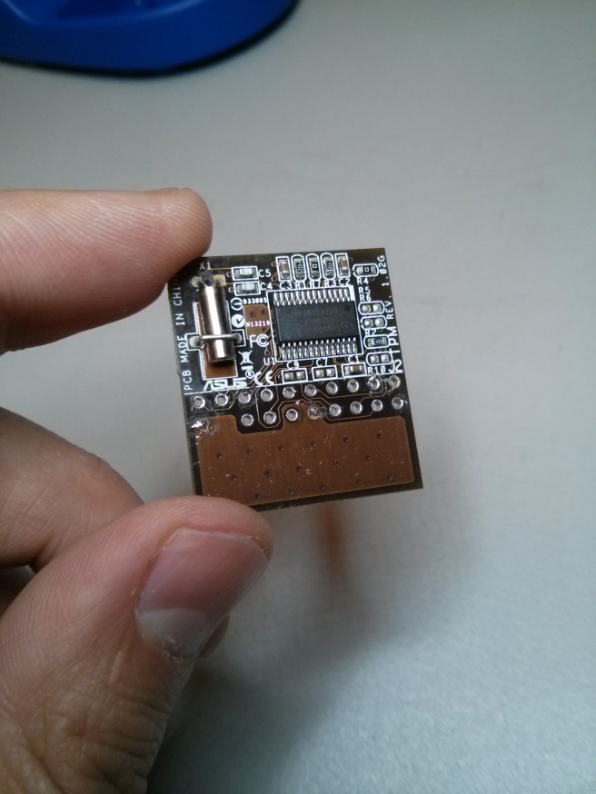
I ordered the parts individually so I could practice my soldering but the end result is the same. Take a few DS1077L+66s from Mouser Electronics along with a few 8-pin SparkFun SOIC to DIP Adapters, solder them together and then plug them into your breadboard. The only difference is that the breakout board from Sparkfun comes with a filter capacitor so we’ll have to supply our own. This oscillator is programmable via the I2C bus so to program the oscillator to the frequency we need we need to wire it up to the I2C bus on a Linux system. In the end the circuit looks something like this.

Top quality CAD drawing for you there. If you’re interested in the details of how this chip works the spec sheet is your friend. The values for the pull up resistors on the I2C lines and the bypass capacitor are specifically defined there. My purposes are simple in that I just need a 33MHz clock so the CTRL pins can be ignored, as can the reference output OUT0. OUT1 will output the clock and SCL/SDA are the two I2C clock and data pins. Initially the DS1077L+66 is programmed to output a 66MHz clock so we’ll need to program the chip to cut this in half.
Programming the DS1077L
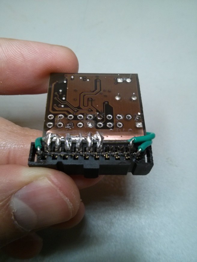
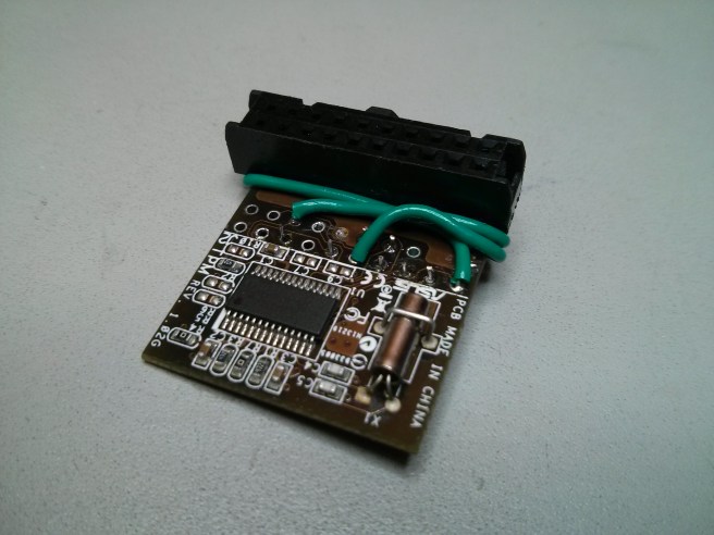
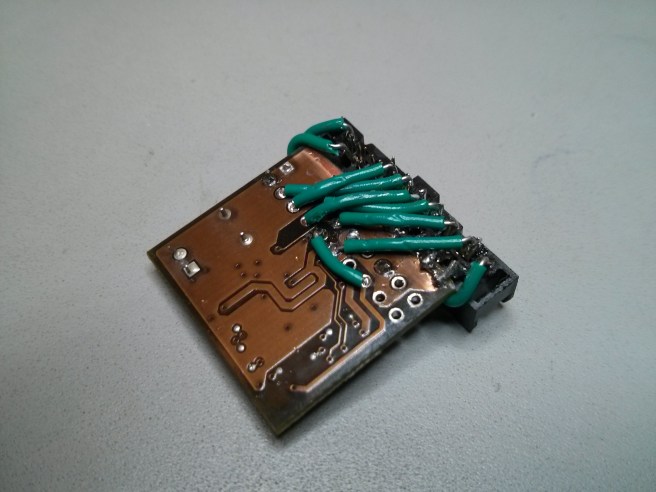
The first step in this process is wiring the circuit and attaching it to the I2C bus on a Linux system. I soldered an I2C header on to my PCEngines ALIX3d2 and hooked it up like so:

This chip is pretty sophisticated so I won’t cover all possible configurations. The data sheet is readily available here so if you want the details have a read (you should anyways if you’re using this chip). All I’m going to cover here is scaling down the clock frequency and the tool I’ve written to do so.
The primary output (OUT1) has two mechanisms for controlling its output. First is a prescaler circuit that can divide the native frequency (66MHz) by 1, 2, 4 or 8. The second is a divider circuit that can divide the frequency by integers between 2 and 1025. The divider circuit can be bypassed completely if we wish so we can get a 33MHz clock in two ways: 1) set the prescaler to 2 and bypass the divider or 2) set the prescalar to 1 and the divider to 2. The DS1077L defines a low power state where much of it’s internal circuitry is disabled including the divider so I opted for this low power state and the first option above.
To aid in programming this thing I’ve put together a small set of tools I’m calling ds1077l-ctrl. These tools expose a simple command interface for modifying the state of the control registers in the DS1077l. As an example we would program this chip to output the 33MHz clock that I need like so:
$ ./ds1077l-mux --bus-dev=/dev/i2c-0 --set --pdn0=0 --sel0=0 --en0=0 --div=1 --p1=2
That’s it. The –help / –usage messages for the tools combined with data from the spec sheet should be all that you need to set the DS1077L to any possible state. In the command above we’ve set (–set) the DS1077L device on I2C bus 0 (–bus-dev=/dev/i2c-0) such that the divider is disabled (–div=1), the prescalar to 2 (–p1=2). The other options (–pdn0=0 –sel0=0 –en0=0) set the oscillator to a low power state disabling the circuitry we’re not using.
To get a sort of before and after I hooked up this chip to an oscilloscope to capture the default 66MHz waveform and the 33MHz one we get after executing the command above:


Bugs
This software is not without bugs (as always). I couldn’t get the WRITEE2 command to work properly but it’s only necessary if you change the default behavior of the chip and set the WC bit to 1. This causes the oscillator to write register state to EEPROM only when the WRITEE2 command is invoked. By default it will save the register state every time it changes so just leave the WC bit alone and everything should work as expected. Alternatively feel free to fix this bug and send me a pull request.